 |
|
| Table Key (& Reference Info) | Model Number Format | Case Marking | Component Evolution |
| 500 Set Colors | G Handsets | When Was My Phone Built? | Contributors -- Many Thanks! |
| RELATED
PAGES ON THIS SITE: 500-STYLE SETS
COLORS
500 SET
DEVELOPMNT BSPs WE 300-SETS WE 1500-SETS WE 2500-SETS PRINCESS SETS TRIMLINE SETS DESIGN LINE SETS WE AUTOVON SETS |
|
Updated: 27
February 2022
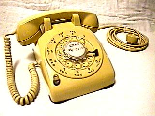
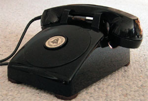
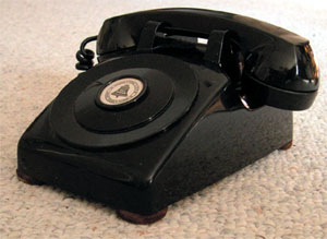
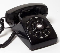
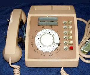
The 500 series was introduced in 1949 and made by the Bell System until 1986. Its design was licensed to ITT in 1951 and other manufacturers during the 50s, until it became the standard. With the later addition of TouchTone, it evolved into the 1500 (10-button keypad), 2500 (12-button keypad), and 3500 (16-button Autovon military keypad) with similar model numbers. |
 |
 |
 |
 |
||
|
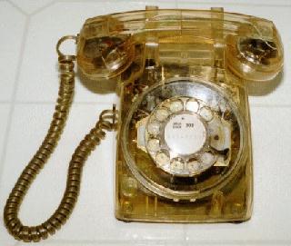
500-type
Rotary
|
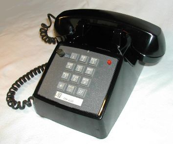
1500-type 10-button dial |
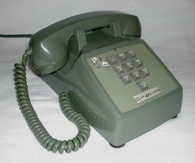
2500-type 12-button dial |
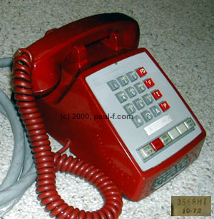
3500-type 16-button dial |
| Over the years,
numerous variations were made with extra switches,
knobs and internal components for special
purposes. Model
numbers well above the 5xx range were ultimately
used. Western catalogs and technical
documentation only show the models that were in
production or service at the publication date.
To understand the full scope of models
produced we must compile data from many years of
documents. This page was created as a casual attempt to answer the simple question, "How many 500-series
models did Western Electric make?"
The question was
first posed to Antique Telephone Collectors
Association (ATCA) and Telephone Collectors
International (TCI) members, and other dealers and
collectors in early 1997. Following
are the results to date (no
claims are made as to accuracy or completeness). For more information,
see the 60th anniversary articles on the
500-series evolution published in the TCI journal,
Singing Wires,
from January thru August, 2009. >> Use: Search (usually Control-F in most browsers) for the last 3 digits of the model number of your set. Or Browse by category, using the links above. Note: the Control-F search only works for models on this page. For Touch Tone models, use the links above to go to the appropriate page, then search.
For more info, go to 500blanks.html.
Looking up the model number for your set should give you a brief description of the major features of the model, and a BSP (Bell System Practices) reference for the rotary set, if known. When available, photos of some unique features are shown near the model number or linked from the chart entry. If you don't find your model listed, try looking up the last 3 digits in the tables for other Western Electric models. Often the major features were consistent among rotary and Touch Tone models. The BSPs provide technical details and usually a wiring diagram. BSPs are often found in the Station Service Manuals, Key Systems Service Manuals and Station Specialties Service Manuals published in the 1970s and early 80s. BSPs or wiring diagrams for some common models are available on several internet sites including the ATCA and TCI club sites. Several club members have scanned some popular BSPs and make them available on CD. For more details on BSPs, click here. You still need to check the internal components as many phones were refurbed and had internal components changed or removed. For example, many phones marked 501D were converted from party line to single line (500D) by removing the 426A tube as party lines lost favor. If done in a Bell System refurb facility, the code on the bottom was usually repainted or remarked. Many independent shops or field mods were not remarked with the accurate model number. Check out the table key for model numbering background and other reference details. |
BASIC SINGLE LINE SETS 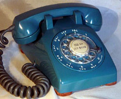 WE500D
|
MODEL |
MAJOR FUNCTIONS |
REF |
BSP |
|
NOTE: see Table
Key for prefix and suffix codes and
reference info. |
|||
 |
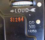
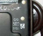
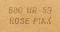
Earliest 500 sets were not marked with
suffix codes. 500 and date were stamped in ink,
usually along the front edge of the baseplate.
|
- |
C38.595.1 Issue 1: 10/58 |
|
|
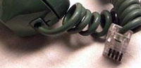
Early single line w/ 425A net &
amp; separate 311A equalizer. Model and date moved to a
location near the ringer, near where the word “LOUD” was
stamped. See Photo.
Replaced by the 500C and 500D. |
2,4,7,8,9 |
C38.595.1 Issue 1: 10/58 502-501-101 |
|
|
Later single line w/ 425 B or E net
and varistors for equalization. (No separate equalizer
needed.)
|
2,4,7,8,9 |
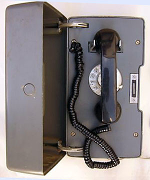
C38.603 502-521-402 |
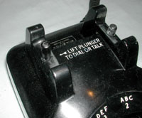 |
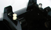
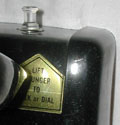
Single line w/ plunger
switch to avoid interference on extensions (or party
lines). Lifting the left plunger activates talk and
dial circuits. Cradle is marked, “LIFT PLUNGER TO DIAL
OR TALK”. Replacing the handset resets the
switches. Replaces the 302AA/AC. |
2,3,4,7,8,9 |
C32.535 Issue 1: 10/58 502-501-115 |
 |
Single line w/ hooded dial lamp (GE46
bulb, 6-8v ac or dc supply, P17A120 lamp cap assembly
[contact me if you have spares of this part!]), 425B
network (or later 425E). The light is only
activated when the handset is offhook.
|
2,3,4,7,8,9 |
C32.535 C32.537 C38.595.00 Issue 1: 10/58 502-501-115 |
|
Single line version of
the 500 (500A and 500B) w/ 425A net and a terminal
block in place of the equalizer.
|
2,3,7,8,9 |
C38.595.1 Issue 1: 10/58 502-501-101 |
|
|
|
Single line w/ A-lead
control for 1A1 or 1A2. 4- or 6-conductor mounting
cord, and terminal strip installed below dial.
Originally used in applications where the ringer
circuit had to be brought out through the mounting
cord. See BSPs for variations and wiring. |
2,7,8,9 |
C32.537 Issue 1: 10/58 502-501-115 |
|
|
Single line w/ hooded dial lamp (GE46
bulb, 6-8v ac or dc supply, P17A120 lamp cap assembly
[contact me if you have spares of this part!]), 425B
network (or later 425E). The light is only
activated when the handset is offhook.
(Available in 1955, MD
ca. 1960)
|
2,3,4,7,8,9 |
C32.535 Issue 1: 10/58 502-501-115 |
|
|
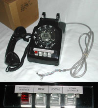
Single line for
speakerphones, including the 1A, 1A1, 3A and 4A.
10-conductor mounting cord, internal terminal strip,
extra dial and switchhook contacts and separate ringer
leads for speakerphone control. See photos
(scroll to bottom of page.) |
1,2,7,8,9 |
C38.595.1 Issue 1: 10/58 502-501-115 |
|
Single line version of the 500 (500A
and 500B) w/ 425A net and a terminal block in place of
the equalizer.
Note: There were no separate model numbers for manual and dial versions.
|
1 |
C38.595.1 Issue 1: 10/58 |
|
|
|
Single line w/ hooded
dial lamp (GE46 bulb, 6-8v ac or dc supply, P17A120
lamp cap assembly [contact me if you have spares of
this part!]). 425B network (or later 425E).
|
2,4,7,9 |
C32.535 C38.613 |
 Photo from Russ
Cowell
|
Single line w/ neon
ringing/message waiting lamp for PBX. Available
in 1958.
|
1,2,4,7,8,9 |
C38.614 502-580-411 |
|
500 AB |
Single
line
for 2-wire or 4-wire circuits. Comes wired for
2-wire service but may be converted at installation to
4-wire service. Arranged for but not equipped
with a KS-8109L2 Buzzer. Intended for use in 1A1
and 1A2 Key Telephone Systems and 3B Speakerphone
Systems, however it is intended for specially
engineered lines. Not for general telephone use. |
6 |
502-510-411
|
|
500 AD |
Single
line
for 4-wire circuits and 3-type speakerphones.
Arranged for 4-wire service and equipped with a switch
hook arrangement which provides one spare transfer and
two spare make contacts. The spare make contacts
may be used for such purposes as controlling external
relays or applying idle line circuit
terminations. Arranged for but not equipped with
a KS-8109L2 Buzzer. Intended for use in 1A1 and
1A2 Key Telephone Systems and 3B Speakerphone Systems. |
2,3,7,8,9 |
502-501-115 502-580-401
|
|
TA236/FT |
Single line with Military
markings on case: Signal Corps US Army, Telephone Set
TA236/FT, Western Electric. |
TM 11-468 |
- |
BASIC PARTY LINE SETS - 426A (or 425A 4-element) tube for 4-party selective ringing
|
MODEL |
MAJOR FUNCTIONS |
REF |
BSP |
|
NOTE: see
Table Key for
prefix and suffix codes and reference info. |
|||
|
501 |
Earliest 501 A/B sets were not marked
with suffix codes. 501 and date were stamped in ink,
usually along the front edge of the baseplate. w/
separate equalizer. First production used C3A ringer,
then C4A.
|
- |
C38.595.1 Issue 1: 10/58 |
|
501 A |
Early party line w/ separate
equalizer.
|
1,2,8,9 |
502-510-400 |
|
501 C |
Later party line w/ varistors for
equalization.
|
2,8,9 |
C38.603 |
|
501 F |
Party line w/ plunger
switch to connect talk and dial circuits - to avoid
interference with talking party. Replaces the
306G. |
2,7,8,9 |
C32.535 502-580-403 |
| 500 H with tube |
Early party line with dial
lamp set. Created from a 500H by adding the 426A
tube. (For some reason apparently not marked
501H.) Single line w/ hooded dial lamp (GE46
bulb, 6-8v ac or dc supply, P17A120 lamp cap assembly
[contact me if you have spares of this part!]), 425B
network (or later 425E). The light is only
activated when the handset is offhook. Cannot be used as the tip party on message rate, automatic ticketing, automatic message accounting or zone restriction services. Replaced by the 501P for these services. |
C38.607 C38.621 |
|
|
501 J |
Party line w/ 425A net w/o equalizer.
|
2,3,8,9 |
C38.609 |
|
501 P |
Party line w/ dial lamp.
|
2,4,7,8,9 |
C38.611 502-510-406
|
|
501 T |
Early Party line w/ 425A net, no
equalizer, but terminal block for handset leads.
Replaced by the 501J and 501K. |
- |
C38.595.00 |
|
501 U |
Party line w/ dial lamp and night light switch |
2,3,7,8,9 |
C38.613 502-510-408
|
OTHER ROTARY VARIATIONS WE 532
|
MODEL |
MAJOR FUNCTIONS |
REF |
BSP |
|
NOTE: see Table
Key for prefix and suffix codes and
reference info. |
|||
 |
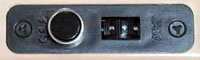
Exclusion Single line w/ extension
set exclusion and A-lead control for 1A2
|
2,4,8,9 |
C32.540 C38.595 502-515-400 |
|
503 B |
Data
|
1 |
|
|
Long loop
|
3,7 |
C38.595.1 Issue 1: 10/58
|
|
|
|
Long loop
|
3,7 |
C38.595.1 Issue 1: 10/58
502-501-116 |
 |
Two line
|
2,4,8,9 |
C32.540 C38.595.02 |
|
510 E |
Two line
Also used on early PBX systems with the switch wired to provide “ground start” during power failures. |
2,8,9 |
C32.540 C38.595.02 |
|
|
Two line
|
2,4,8,9 |
C32.540 C38.595.02 |
|
511 C |
Two line
|
2,8,9 |
C32.540 C38.595.02 |
|
511 F |
Two line
|
2,8,9 |
C32.540 |
|
511 H |
Two line
|
2,8,9 |
C32.540 |
|
511 X30A |
Voice Coupling using 30A
Voice Coupler.
|
- |
502-501-901SW |
 |
With key for Secretarial
exclusion |
- |
511 modifications |
|
513 B |
Early Data-Phone
|
4 |
C38.595 C38.627 |
|
|
Headset Jack
|
2,7,8,9 |
502-501-115 502-580-412 |
|
|
Two line
|
1,2,4,8 |
502-515-105 Issue 1:
4/66 |
|
|
Single line
|
2 |
502-580-463 |
|
"Explosive atmosphere"
|
2,5 |
C38.595 502-415-100 502-415-203 |
|
|
“Elevator” phone.
|
- |
- |
|
|
Weatherproof housing
|
2,9 |
C38.821 502-501-117 |
|
|
Weatherproof housing
|
2,4,8,9 |
502-501-117 |
|
|
529 A |
No network, 12 conductor
cord for 101- and 102-key equipment. Available in
black only. Replaced 329C set.
|
- |
502-560-109 |
 |
Impaired Hearing Single line w/ receiver amplification
and volume control. 151A amplifier, 419A
varistor, and P13A693 potentiometer. |
3,7 |
C38.595.1 Issue 1: 10/58
502-501-116 |
|
|
Impaired Hearing
|
3,7 |
C38.595.1 Issue 1: 10/58
502-501-116 |
|
535 A |
|
7 |
C38.595.1 Issue 1: 10/58
502-501-116 |
|
|
Single line w/ speech
amplification. Useful for whispered confidential
conversations.
|
3,7 |
C38.595.1 Issue 1: 10/58
502-501-116 |
537A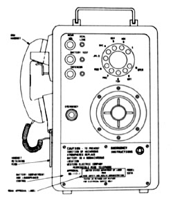 |
Rotary dial telephone e/w
G5U handset, flush mount loudspeaker, battery test
button, RCVR VOL pushbutton, emergency button. 12V
dry cell battery for 3 months of average use. Mechanically rugged, portable, corrosion resistant, "sealed against 100-percent humidity and forceblown rock dust." (!!) Operates at -18 to 60 degrees C (0 - 140F). Meets requirements for "Intrinsic Safety" in Mineral Resources, Title 30, Part 23 (Telephone and Signaling Devices), UL Standard 913 and National Fire Protection Association 493. Approx. 18.58 in x 14.04 x 9.56. 28 Pounds. Initial Use: No. 1A Industrial Communication System Comcode: 103 222 592 |
WE Card Index 5/29/81 Found by Rick Walsh |
|
|
540 - series |
See Key Sets |
- |
- |
|
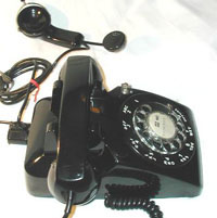
55x are all wall sets
 |
Single line wall w/
exclusion plunger on top. |
7 |
500-124-180 |
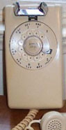 |
Single line wall. Announced in 1955 in black and ivory.
|
2,4,7,8,9 |
C32.559 Issue 1: 2/55
C38.637
502-521-410
|
|
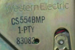
554 F |
Single line wall equipped
with 9 foot handset cord. |
2,4,7,8,9 |
502-501-101
|
|
555 B  |
Two line wall w/ signal key and hold button |
2,8,9 |
502-515-415 |
|
|
Party line wall |
2,7,8,9 |
C32.559 Issue 1: 2/55
C38.595.1 C38.637 502-501-101
|
|
|
Long loop
|
7 |
C38.595.05
502-520-400 |
|
558 A |
|
2,4,8 |
C32.559 Issue 1: 2/55
C38.638 502-515-401 |
|
558 C |
Two line wall
|
2,7,8,9 |
502-501-116 502-515-100 |
|
558 F |
Two line wall
|
2,9 |
502-515-100 |
|
|
Long loop
|
7 |
C38.595.05 502-520-100 |
|
560 - series |
See Key_Sets |
- |
- |
|
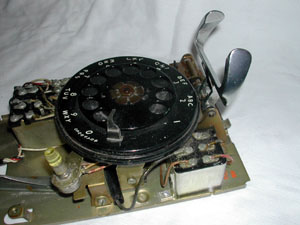
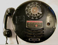
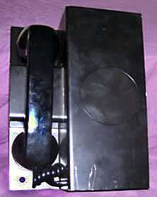
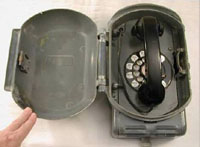
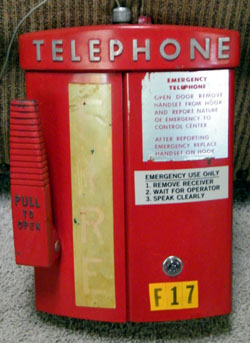
570
Photos
from John Corley
|
Large
roadside "Emergency Reporting" or "Fire" set, manual
only, Usually painted bright red or yellow.
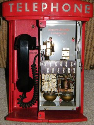 Cover removed to
show internal components.
|
8,9 |
C38.813 C56.112 |
| 575 |
See Key_Sets | - |
- |
|
Telephone Set Base Internals for
customer-supplied housing and handset. |
2,8,9 |
503-100-120 |
|
|
|
Desk set supplied to
operating company with no Bell System markings or
ringer -- for installation of a frequency selective
ringer for party line use. |
- |
No BSP - see 500D Connection |
|
Single line set with
internal speakerphone microphone and controls -- used
with 1A and 1A1 Speakerphone systems. See
details and photos |
4 |
C70.201.00 C70.201.01 C70.201.03 512-610-100 512-610-101 512-610-200 512-610-400 |
|
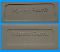
|
|
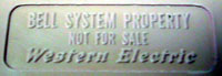
Wall set sold to independents without a ringer, marked "Western Electric" See photos |
10 |
No BSP - see 554 Connection |
|
596 E |
"This is a desk type
manual telephone set intended for use in the Command Post Alerting Network
(COPAN)."
|
- |
C38.595.01
529-205-148 |
|
597 AR |
"Used in the (SAC)
Strategic Air Command secondary and primary alerting systems."
|
- |
502-536-100 |
|
660 - series |
- |
- |
|
|
750 - series |
- |
- |
|

ROTARY KEY SETS
WE 544
|
MODEL |
MAJOR FUNCTIONS |
REF |
BSP |
|
NOTE: see Table
Key for prefix and suffix codes and
reference info. |
|||
|
|
4-button, non-lighted buttons PS = pickup,
locking, convertible to signalling, non-locking 500-series keysets
announced in 1955. |
- |
502-525-200 C32.558 |
|
|
4-button, non-lighted buttons and exclusion, 14-conductor line cord |
7 |
500-124-180 |
|
543 |
4-button,
single line, specific to a 761A PBX
543DB – 641A line key, C4B ringer 543DBC – 588B line key, C4A ringer –
field/distributor converted from 544BB or 545BB. |
- |
502-522-100 502-580-431 |
|
|
4-button, lighted
buttons.
|
- |
C32.558 |
|
|
4-button, lighted buttons and exclusion.
|
7 |
500-124-180 |
|
6-button, non-lighted buttons and exclusion. 25-pair line cord. |
- |
C38.595 C38.595.3 |
|
|
6-button, headset connection. 25-pair line cord. |
7 |
500-124-180 502-541-404 |
|
|
564 |
B: H P P P P P, 28-conductor
line cord D: H P P P S S, 25-conductor line cord
|
- |
C32.558 502-525-102 502-541-407
|
|
565 |
6-button, lighted
buttons and exclusion A: P P P PS PS PS, 34-conductor line cord B: H P P PS PS PS, 34-conductor line cord E: H P P P PS C, 31-conductor line cord Later
sets
with speakerphone and 25-pair line cord: There
was a modificatied 565 with speech amplifier
added.
|
7 |
C32.558 500-124-180 502-541-410 502-541-414 502-541-415 502-541-416 |
|
6-button, used with 755A PBX
|
- |
C38.851 |
|
|
6-button Data Aux Set
|
7 |
500-124-180 502-501-122 |
|
|
568 H |
6-button w/ exclusion
(HB,HF,HR,HT) 2 or 4-wire operation (P25E963
relay assembly).
|
7 |
C38.642 C38.642.00
|
|
568 HT |
Early touchtone keyset
(before 1500 numbering), relay for 2 or 4-wire
operation.
|
7 |
C38.595.06
|
|
569 NB |
Data Service
|
7 |
502-501-122 |
| 575 AM |
6-button keyset for Comkey system
intercom-only stations Comkey 718, 734, 1434 and 2152. Red non-functioning key may be used for message waiting, 3 intercom line keys and 2 unused keys. |
- |
503-603-120 518-450-110 Issue 1: 1976 |
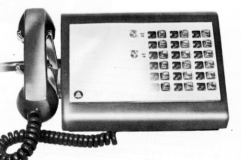
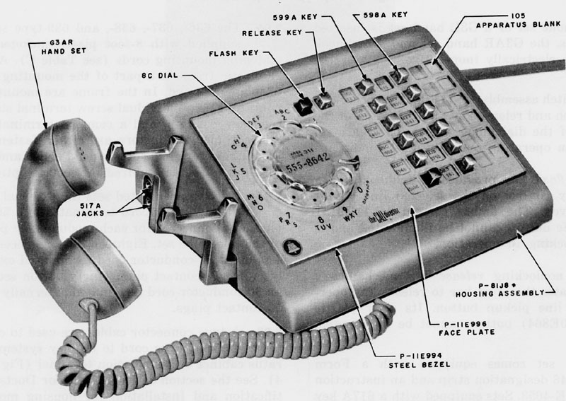
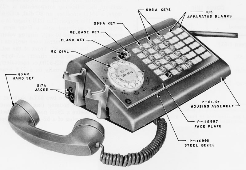
 (CLICK IMAGE FOR LARGER VIEW) |
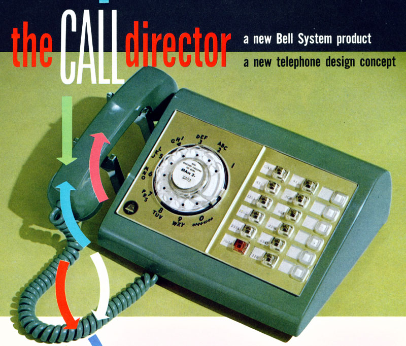
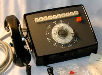
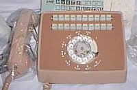
This
section contains Call
Director sets, which were introduced in 1958,
and "Call Director-type" telephone sets and consoles
made from similar components and contained in related
BSPs. Similar touch tone sets can be found on the 1500-, 2500- and 3500-series pages: 1500-series CallDirector 2500-series CallDirector 3500-series (AUTOVON) CallDirector |
||
600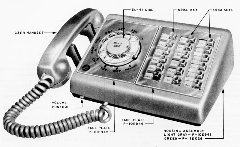 (CLICK
IMAGE FOR LARGER VIEW)
601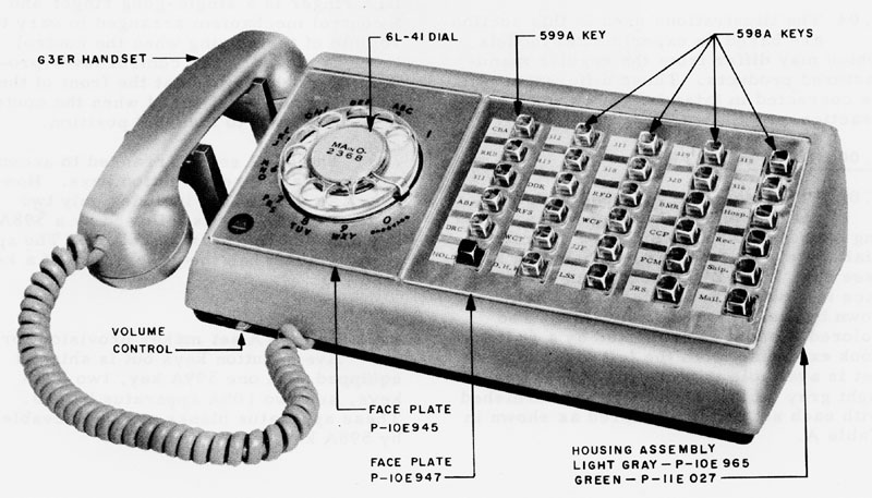 (CLICK
IMAGE FOR LARGER VIEW)
|
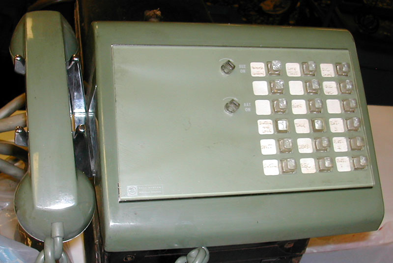
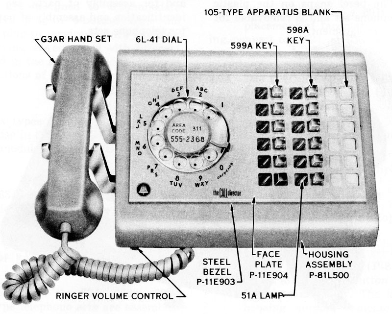
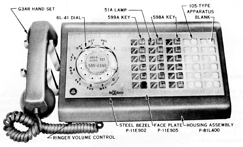
Call Directors, General Purpose 18-button 30-button D1A Ringer (adjustment on front left of set), 6L dial. For 1A1 and 6A Key Telephone Systems, NOT 1A. Call Directors announced in 1958. Replaced by the 630-series. |
- |
C38.650 Issue 1: 1958 C38.653 502-630-101 |
|
608 |
Call Director 2 or 4-wire 608C with headset jack,
Flash and Release keys. |
- |
C38.655 |
609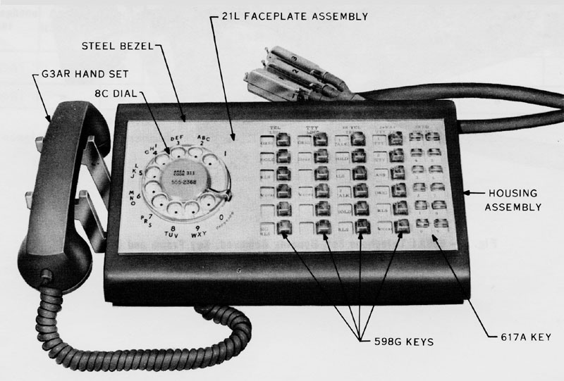 (CLICK
IMAGE FOR LARGER VIEW)
|
Call
Director, used at supervisor desk with a dial TWX or
WADS No. 6A teletypewriter switchboard. Moss green (-51). 589G keys (4) plus 617A Key. |
- |
502-609-101 502-609-401 |
616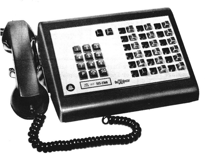 (CLICK
IMAGE FOR LARGER VIEW)
|
Call
Director, 18-button, used with Switched Circuit
Automatic Network (SCAN). 2- or 4-wire circuits, 1A1 or 1A2. Flash and Release keys. Moss green (-51). 22B TouchTone dial with P and SG keys (like the 568HT above.). Replaced by (renumbered to) the 1616 shown here. |
- |
C38.658 502-616-120 502-616-401 |
| 617 |
Call
Director, 30-button, used in FAA installations. 2- or 4-wire circuits. Light Gray (-61). |
- |
C38.658 502-616-101 502-616-402 |
|
618 |
Call Director, 2 or
4-wire service. |
- |
C38.655 |
619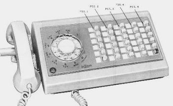 |
Used
with
5A Announcement Systems |
- |
WE Tel.Prod HB, 1975 201-511-101 201-511-301 201-511-501 |
| 621 |
Used
by
701B PBX attendant. |
- |
C38.656 502-620-400 |
| 622 |
Used
in
No. 5 crossbar systems arranged for customer group
service. |
- |
C38.656 502-620-401 |
| 623 |
Used with Master Control Center of Electronic Switching System Offices. Light Gray (-61). 18-button. | - |
502-623-100 (Issue 1: 9/64) (Restricted Distribution) WE Tel.Prod HB, 1975 |
| 624 |
Used
with
the recorded announcement frame of the No. 1 Electronic
Switching System (ESS). |
- |
WE Tel.Prod HB, 1975 |
|
625
(CLICK
IMAGE FOR LARGER VIEW)
|
Call Director, used with the 110A key
telephone system.
Turnkeys for battery and
buzzer. G5 push-to-talk handset. |
- |
500-124-180 |
|
631 630-type with Speakerphone
(Photo from John Decker)
|
General
purpose
Call Director Replaced 600A and
601A.
|
- |
C38.651 502-600-100 502-600-101 502-600-301 |
| 632 | Call
Director
for "limited use" 18-button Replaced 600B. For 1A1, 1A2 and 6A Key Telephone Systems, NOT 1A. |
- |
502-600-100 502-600-101 502-600-301 502-630-101 502-630-402 |
|
634
(CLICK
IMAGE FOR LARGER VIEW)
635
(CLICK
IMAGE FOR LARGER VIEW)
|
Call Directors used with station line
concentrators 18-button
|
- |
C38.650 502-600-100 502-600-101 502-600-301 |
|
636 637
Looks like
this 683 set
Photo from Dave Friedman |
General
purpose
Call Directors with headset jack 18-button Flash and
Release keys above dial. 151D amplifier. |
- |
C38.650 C38.651 502-600-100 502-600-101 502-600-301 |
|
638
(CLICK
IMAGE FOR LARGER VIEW)
639
(CLICK
IMAGE FOR LARGER VIEW)
|
Call Directors with headset
jack used with station line concentrators 18-button 30-button Flash and Release keys above dial. 151D amplifier. Uses "even count" color codes. For 1A1, 1A2 and 6A Key Telephone Systems. |
- |
C38.651 502-600-100 502-600-301 |
| 643 |
Call
Director,
used in the 11A Alerting System. |
- |
WE Tel.Prod HB, 1975 |
|
66x |
- |
- |
|
| 680 681 |
Call
Director,
"Not for general telephone use. Shall not be used unless
specified by service order." 18-button 30-button |
- |
WE Tel.Prod HB, 1975 |
| 682 683
Photo from
Dave Friedman
|
Call
Director,
for 2- or 4-wire operation. 18-button 30-button |
- |
502-601-101 502-610-412 WE Tel.Prod HB, 1975 |
|
Subset used with data set
101A in Models 14, 15 and 19 teletypewriters.
|
- |
C38.061.01 (Issue 1: 12/62)
502-200-101 |
|
|
750 - series |
- |
- |
|
|
10-button desk set
|
- |
503-701-101 |
|
|
20-button desk set |
- |
503-702-101 |
|
| 832 |
10, 11
or 13- button keysets used in Comkey 718 and 2152
systems (see BSPs) 11-button sets have HOLD, 7 line pickup, 2 intercom lines and RECALL. 13-button sets add Privacy Release and Ring Transfer Variations for both desk and wall mounting. |
- |
503-701-110 518-450-110 |
| 833 |
20-button keysets used in Comkey 718
and 2152 systems (see BSPs) HOLD, 14 line pickup, 3 intercom lines, RECALL and Privacy Release -OR- Ring Transfer. Variations for both desk and wall mounting. |
- |
503-702-110 518-450-110 |
| 835 836 |
10-button keysets, Comkey
416 Primary station with power supply and logic.
(see BSPs) 10 key Direct Station Select field. (Replaced by 981 sets) |
- |
518-450-105 518-450-106 |
| 837 |
10-button keysets, Comkey 416 Satellite
station without power supply and logic. (see BSPs) 10 key Direct Station Select field. (Replaced by 981 sets) |
- |
518-450-105 518-450-106 |
|
6-button wall set |
- |
503-601-101 |
|
|
10-button wall set |
- |
503-701-102 |
|
| 981 |
10-button keysets, Comkey 416, 4A
Communication System Primary (981A01) and Satellite stations (981A02 desk, 981A03 wall). (see BSPs) 10 key Direct Station Select field. |
- |
518-450-105 518-450-106 |
| 983 |
10-button
keysets, Comkey 416, 4A Communication System Satellite stations with BIS (built-in speakerphone, 983A01), or HFAI (Hands-free answer intercom, 983A02). (see BSPs) 10 key Direct Station Select field. |
- |
518-450-105 518-450-106 |
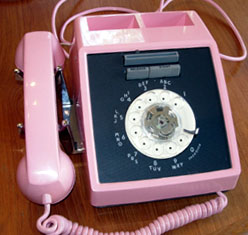
ROTARY AUTOMATIC DIALERS 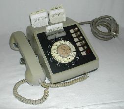 WE 661
|
MODEL |
MAJOR FUNCTIONS |
REF |
BSP |
|
NOTE:
see Table Key for
prefix and suffix codes and reference info. |
|||
 |
Automatic Dialer - 41-type dial, C4 ringer, 4010B
network. 4228-type
network and C4-type ringer used in later production. |
- |
C38.668.00 (Issue 1: 3/63)
502-660-120 502-660-100 502-600-102 502-000-111 502-617-400
|
|
|
The 661 was the
first card dialer model announced. Keyset, 6-button
Automatic Dialer - 40A dial, G1A ringer, 4010-type
network.. |
- |
C38.665 (Issue 2: 4/61) C38.665.00 502-661-101 502-601-130 502-617-401 502-601-131 502-617-406 |
 |
Keyset, 6-button
Automatic Dialer - 41A dial, optional exclusion
feature, wired for speakerphone use.
|
- |
C38.666.00 (Issue 1: 1/63)
502-660-102
502-617-402
502-617-406 |
|
663 |
Automatic Dialer - 41A dial, wired
for headset use, has 242-type amp, jack on the left
side and turnswitch for ON/OFF control. |
- |
502-660-120
|
|
Keyset, 6-button Automatic Dialer - wired for headset use, has 242-type amp, jack on the left side and turnswitch for ON/OFF control. Requires a low voltage external power supply for operation. |
- |
500-124-180
502-601-130 502-617-404 |
|
|
665 |
Automatic Dialer for 2 or 4-wire service. Requires a low voltage external power supply for operation. |
- |
500-124-180 |
ROTARY PANEL PHONES
|
MODEL |
MAJOR FUNCTIONS |
REF |
BSP |
|
NOTE: see
Table Key for
prefix and suffix codes and reference info. |
|||
|
750 A |
Single line panel
phone.
|
7 |
C38.680 502-705-100 502-730-401 |
|
2-line panel phone with
exclusion.
|
7 |
502-733-401 |
|
|
751C 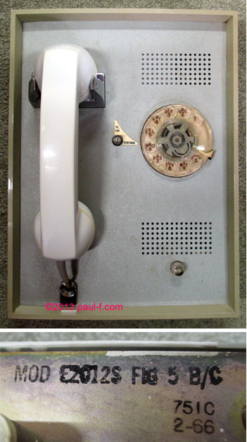
|
2-line panel phone with
exclusion.
|
7 |
502-705-101 |
|
752 |
Panel phone with 3-type speakerphone. |
- |
502-705-102 |
|
753 A |
2-line panel phone with hold |
8 |
502-705-103 |
|
754 |
6-button keyset panel
phone |
- |
502-705-102 |
|
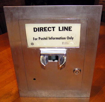
Photo from Jeremy Walters
|
Armored, with armored cord (like a pay phone). Used in lobbies to communicate with tenants. |
- |
502-750-105 |
|
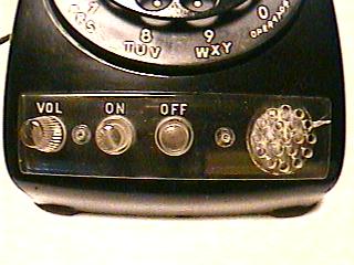
MODEL
Number
Format = 5nnv,
where 5nn=model number, and v indicates model
variations.
• Many TouchTone models have similar numbers, with a prefix of 1, 2 or 3, e.g. 15nn x/y. (See the appropriate site page for touch tone models. Links at the top of this page.) • Prefix codes:
3: Autovon models,
16-button keypad (adds FO, F, I and P keys),
e.g. 3504B, announced 1969;
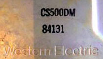
CS: later models
(1980s) which were customer-owned (including internal
components), e.g. CS2500. • Suffix codes (Note:
multiple suffix codes may be used on one set):
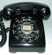
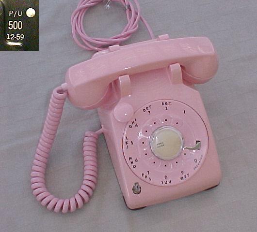
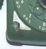
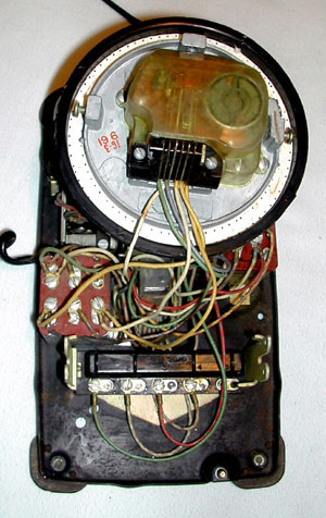
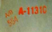
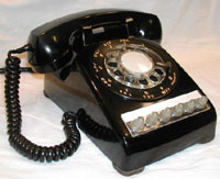
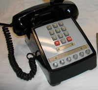
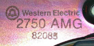
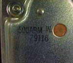
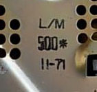
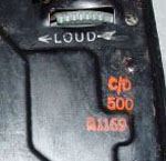
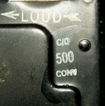
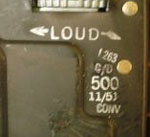
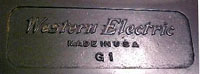
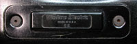
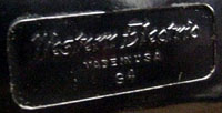
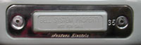
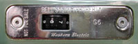
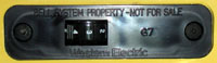
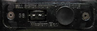
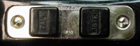
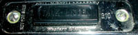
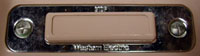
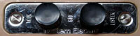
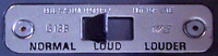
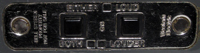
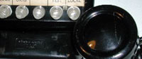
• Note: WE made many models based on the 500 design with model numbers outside the range 500-599. SAMPLE MODEL AND DATE MARKINGS: The markings are usually found in the back right corner of the bottom plate -- either below or to the left of the ringer adjustment wheel.
Note: date codes on the right two phones are in the form YYDDD, where YY is the last 2 digits of the year and DDD is the numeric day of the year (001-365). Their bases are cad plated, rather than the original black. Date codes changed format in about 1978 for 500-type sets and in about 1977 for Princess sets. • COMPONENT EVOLUTION: Model numbers relate to "function" while components in each model changed from time to time, and were often phased gradually into production. For example, in the 500D:
(Many
individual components have date codes. It is
not uncommon to find refurbished phones with
internal components of mixed dates, as the Bell
System was a master of recycling. I have
several sets with 2 leather feet and 2 plastic feet
thanks to the refurb shop. The real treasure
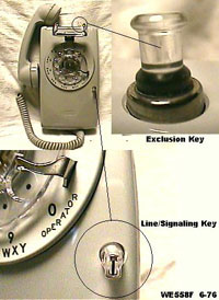
is to find an early set where all the dates match!) • Exclusion keys were wired for many purposes, including ringer cut-off, extension station cutoff, etc. References
include:
|
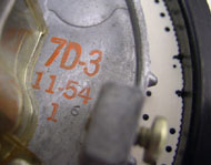
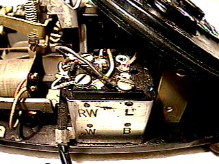
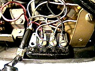
WHEN WAS MY 500-TYPE SET BUILT? It's time for some detective work. Fortunately, Western Electric left a lot of clues for us to follow. Most components of the 500-series sets had both model numbers and dates. This was important for them, as the Bell System owned the phones at the time, and refurbished the sets to extend their useful lifetime. Most of the sets we find today were in service for many years and were probably refurbished at least once. Original components were replaced with the currently manufactured parts. Therefore, internal dates of the components do not always match. The dates that are the most important in establishing age are the date on the bottom plate and the date on the network. These two components were usually joined in the assembly process using rivets, so were difficult to change in refurb. If the dates match, that was most probably the assembly date of the phone. Other components used in the assembly would originally have had the same month code or perhaps a date a month or two earlier. Look at the model number and date information carefully, to make sure it hasn't been changed. Often, original dates have been painted over and new dates stamped .
Parts such as the dial, ringer, cords, plastic housing and all handset components usually also have dates. These parts are real easy to change, so were often replaced during the phone's useful lifetime. If your phone has mixed dates, the interesting dates for it are the dates on the base and network, and the dates of the last refurb or newest component found. Another exercise for the phone sleuth is to try to determine what the original model number was, if the original model number had been painted over. Occasionally careful examination of the black paint will show a slight raised pattern caused by the original ink below. In other cases, remains of the previous model will be left in place. For example, looking inside the phone from the rightmost photo above revealed a terminal strip near the handset entry hole. Therefore the original set was probably a 500T, 500J or 500K. The original 425A network had been removed and replaced with a 425B. The terminal strip was left in place. Phones stamped "CONV" usually had the network replaced. The conversion was from the 425A to 425B. |
Now that you know how many models you need to collect, try finding them in all the following colors, by year!! The color code was appended to the model number as a suffix. Dates offered are included, where known. To view 1983 Western Electric Color Charts, follow these links: For Phones , or For Components . (Thanks to Todd Bernstein and David Massey for providing these charts!) |
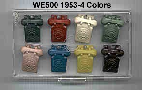
Keychains in "original" colors
|
WE 500 Colors: 1949 thru 1983 Note:
The
first color name is typically the one found in the
initial BSPs. Other names were used in marketing
literature and often differed among the Operating
Companies. New
in 1953 (Black handset, dial
& cord) New in 1954
(full color or two-tone) New in 1957
(two-tone MD) New in 1964 *MD = Manufacture
Discontiued |
-115 Royal Blue, Dark Blue Peach
|
|
How
simple could it be? Although we usually find the
G1, G3 and G15 versions, look at all the others out
there... |
| MODEL TYPE |
DESCRIPTION |
BSP |
|
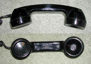
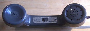
G1 |
Early standard
handset - Bakelite Housing and Caps, Black.
|
C63.341 501-210-102 501-210-300 |
|
Early push-to-talk/listen. Replaced by G5. |
C63.341 501-210-102 501-210-300 |
|
|
G3 G3W photo (no Bell
System markings)
from Jonathan Sowers |
Later standard
handset - Plastic Housing and Caps. Available in
colors.
|
C63.341 501-210-102 501-210-300 |
|
|
with Shoulder Rest - fits into two holes on
handle.
Models
include:
G4AR (black only), G4B (colors), G4M
(modular). Announced in 1954. |
C63.341 501-210-102 501-210-300 |
|
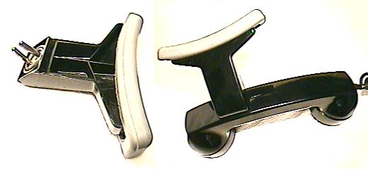
G5 |
Push-to-talk - Has
a rectangular push-to-talk bar on the handgrip. Models
include:
G5AR (mobile radio), G5BR (4-wire circuits,
paging),G5CR (FAA, private line systems), G5ER
(535 set), G5FR (Bendix MRT9 radio), G5GR
(2,4-wire private line stations), G5HR (102-type
key equipment), G5JR (#300 switching system), G5KR
(2A farm interphone), G5LR (617 set, COPAN), G5MR
(Air-ground base station), G5NR (625-type set),
G5PR,RR (596E set). |
501-210-102 501-210-300 |
|
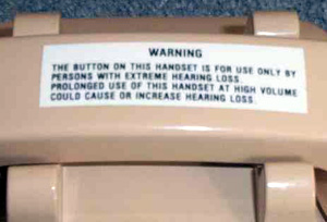
Impaired Hearing
- receiver amplifier and volume control in
handset.
|
501-210-300 501-211-102 501-211-400 |
|
|
Weak Speech - transmitter amplifier and volume control in handset. |
501-210-300 501-211-102 501-211-400 |
|
|
Noisy Locations - receiver amplifier with volume control and push-to-listen switch, which decreases transmitter output and increases receiver output. |
501-210-300 501-211-102 501-211-400 |
|
| D-180413 |
Modified G8B for noisy locations -
provides additional receiver gain. (See G66.) |
501-211-102 Addendum I1 |
|
G10 |
Used primarily by
Government Agencies for Security Reasons - To listen or talk
it is necessary to depress a button in the middle of
the handset.
Models
include:
G10A-F.
C
has an H6F cord with 425A plug.
|
501-210-301 Tel. Apparatus and Equip. 1/70 |
| G11 | "Used with 15A, 15B and 15C apparatus
which are part of 520A, 520B and 2520C explosion-proof
telephone sets. Designed to provide protection against the probability of explosion resulting from flames originating within the handset under extreme conditions of operation." (Makes you wonder about the rest of the handsets, doesn't it?) T3 transmitter, LA1 receiver, aluminum lined cavities. |
501-210-102 (added before
issue 9) |
|
Early plug-in type cord
|
501-210-103 | |
|
G13
G13B - photo from
Steph Kerman
G13D - photo from
Jeremy Walters
|
Amplified Receiver
for public telephones
G13B - photo from
Steph Kerman
Later G13D handsets
used two pushbuttons. Push and hold either for
10db or both for 20db gain. Available in -52 gray or
-104 chocolate brown.
|
____________ 501-211-102 issue 2 or later 501-211-400 |
|
Basic handset with modular
connection.
|
501-210-103 | |
|
G36 |
|
501-211-103 |
|
G66 |
 |
501-211-102 Issue 6 |
|
GF |
Uses a G1 or G3 handle,
with adapters for HA1 and F1 elements used in the F1
handset. See
photo |
502-400-301 NY |
|
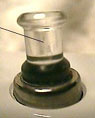
This is actually a receiver that
looks like a G3 handset.
|
502-200-101 | |
|
KS-16504 |
High fidelity dynamic
microphone.
|
501-210-120 501-210-300 |
J1 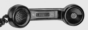 |
Control of 1-type telephone reporting
set from a remote line. Similar to G5 with a
switch controlled oscillator for generating a 1475 cps
signal. |
501-210-104 |
| Link to similar info on F Handset Models. | ||

| Note: Early models had separate cord retainer parts in the transmitter cavity. Later models had the retainer molded into the transmitter cup. The parts are not interchangeable. |
Please send comments or photos of your favorite phones to:

Donation
of
photos (or actual phones) is greatly appreciated.
CONTRIBUTORS
Thanks to ATCA and TCI members, including: Rick Walsh, David
Massey, Jeremy Walters, Todd Bernstein, David Willingham, John
Chalupsky, Steve Hilsz, Steph Kerman, Stan DeOrsey, Steve Schlink, Jonathan Sowers and Vern
Potter.
Free counters provided by Andale .
©1997-2022 paul-f.com. All rights reserved.