 |
|
|
RELATED
PAGES ON THIS SITE: DEVELOPMENT
OVERVIEW TOUCH
TONE DEVELOPMENT TIMELINES
WE 300-SERIES WE 500-SERIES WE 1500-SERIES WE 2500-SERIES WE AUTOVON SETS WE Princess |
This is a work in progress. Please send additions and corrections. I'm sure there are many "missing links" to be discovered. For background, read the DEVELOPMENT OVERVIEW. |
|
WE 302 development timeline -- announced in 1936 Design goal: Produce a combined set (telephone and subset in one compact unit). |
|
 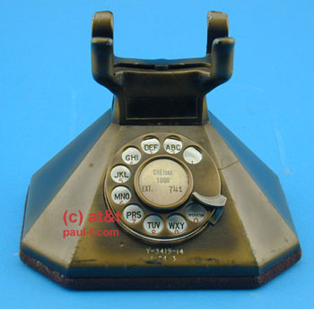 |
1929 Octagonal base concept, wood design model Y-3290 7/10/29 An interesting alternative to the rounded D1 mounting. 1931 Concept set, wood design model Y-3419-19 1/24/31 Combined set using some design cues from the D1 mounting and octagonal design above. (Images courtesy of AT&T Archives and History Center, San Antonio.) |
|
|
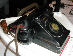
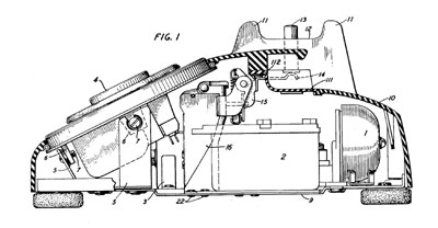
1932 D-95647 IV 32 Long metal case with ringer positioned in the rear. Details... |
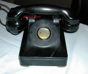 |
1936 D-97464 I 36 & II 36 Short case looks very similar to the production model. Found with either bakelite or metal housings, with a metal base plate. Later models had a F1-like handset. Details... |
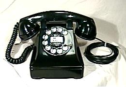 |
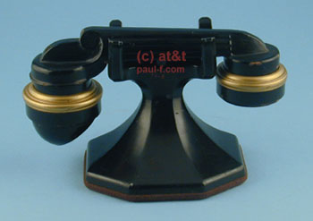
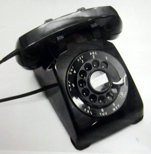
1936 -- WE 302 as
announced Original cradle accommodated both E1 and F1 handsets. Case was cast metal, baseplate was metal. For details on models produced, go here: WE 300-SERIES |
 |
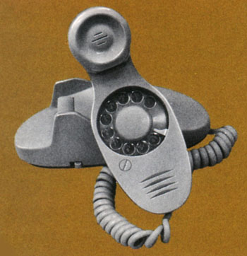
Prototype for a
15-line keyset. (Courtesy of Lucent.) |
500 desk set development timeline -- announced in 1949 Design goal: Produce a set that compensates volume level for distance from the central office. |
|
   |
1946 - Henry Dreyfuss'
firm began work on the 500 external design. Effort
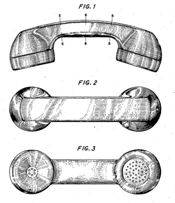
led by Robert Hose. Some 2500 sketches were made. Handsets were primarily modeled in wood, while bases were initially in clay and the most promising cast in plaster and lacquered. (References: Designing for People, Henry Dreyfuss, Simon and Schuster, 1955; Designing the Telephone, Bell Telephone Magazine, Summer 1955; Henry Dreyfuss, Industrial Designer: The Man in the Brown Suit, Russell Flinchum, Rizzoli, 1977; A Conversation with Donald Genaro, Singing Wires, Vol 18, No 10, Oct 2004.) June 1947 - G handset Design Patent filed. March 1948 - Base Design Patent filed. Sept 1948 - Line Switch Patent Application filed. Housing shape updated. April 1949 - Ringer Patent Application filed. 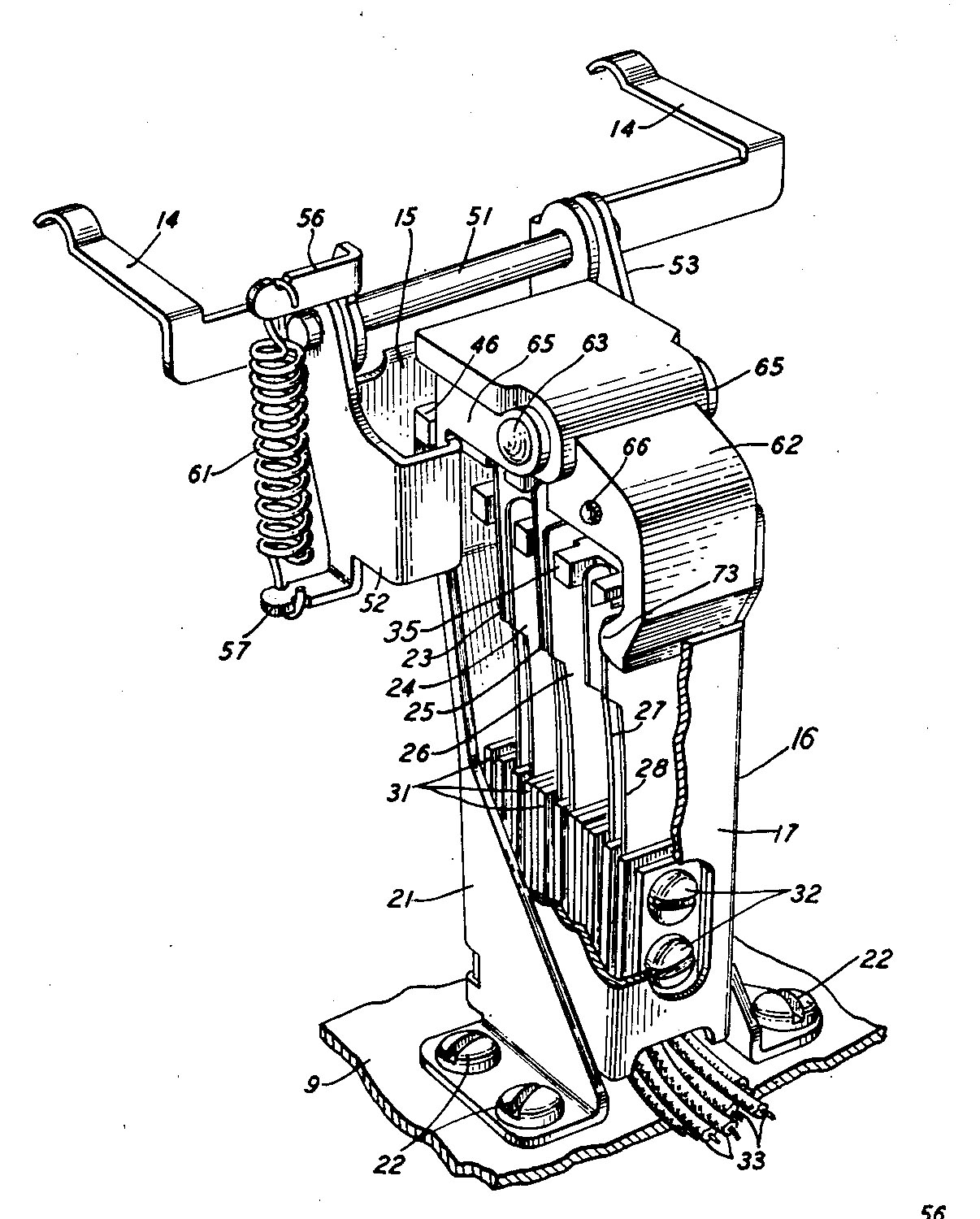
 (Click
on image for larger view)
Hookswitch: Arms changed from horizontal to vertical orientation for before production. Mounting and dust cover design simplified. Ringer: Casting redesigned to permit 2 mounting screws instead of 1 before production. |
 |
1948
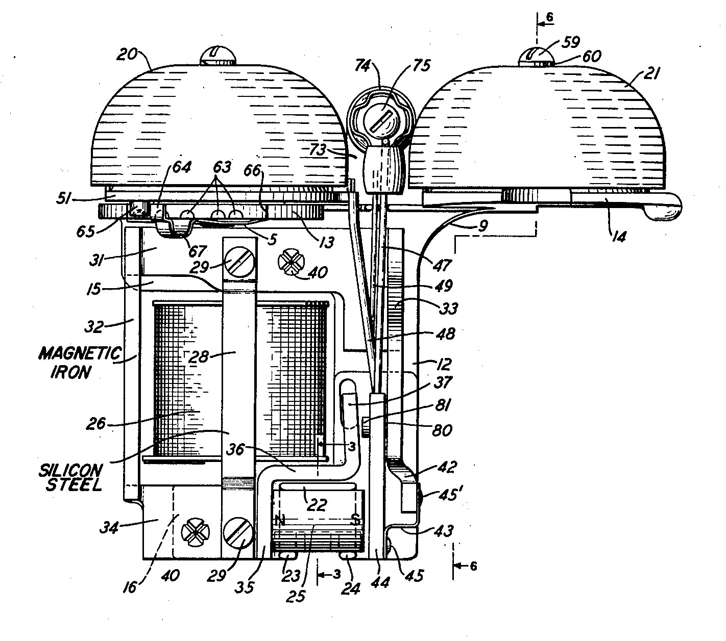
Pre-production. (Best guess based on research to date. Watch for updates.) Internal components similar to the patent drawings. Aluminum dial mount. Plastic fingerwheel. Bell coil wrapped in olive cloth (like 302s B1A). Aiming dots, visible through the fingerwheel holes, were added during the development process to help improve dialing speed and accuracy. Field Trial of 50 pre-production sets. (BSTJ*, 4/51) (Photo from Pacific Tel Magazine, May/June 1949.) *Bell System Technical Journal |
 |
1949, November. Internal components modified to satisfy manufacturing and service considerations. Metal fingerwheel. There were several configurations of the dial ring, with different legends at the "0" location. One has 0, OPERATOR, and Z (as the set above). Another has 0 with OPERATOR underneath in an arc. Field Trial of 4000 early production sets in 10 locations, including Manhattan, Staten Island, Chicago, St. Paul, St., New Orleans, Los Angeles and San Francisco. (BSTJ, 4/51) Also St. Louis. (From an internal Bell System memo in the AT&T Archives) Go to component comparison photos. |
| |
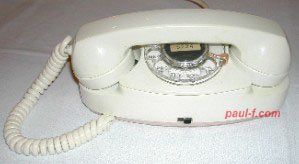
1949 -- WE 500 as announced June 2, 1950, "The first supply of new 500-type telephone sets was announced. About 180,000 were expected to come off production lines during the balance of the year." (Events in Telecommunications History, AT&T) For details on models produced after introduction, go here: WE 500-SERIES (Photo of a dial dated 10/49 in a 1950 phone. This dial ring style was used until mid-1950.) |
| Use
this link to the Touch Tone Desk Set Timeline To Touch Tone Development Timeline |
|
Princess development timeline -- announced in 1959 Design Goal: Produce a compact set with lighted dial suitable for a bedroom extension. |
|
 |
ca. 1955 - 1956 Numerous design concept models were made from wood. Additional sets... |
 |
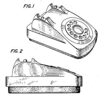
1957 F51910 3/57 - "Bedroom Telephone" Full size dial (#6 style), Light switch on front. Electronic Ringer or F52510 external ringer. Product trials in Columbus, OH and San Leandro, CA. 400 sets in each city. Tested with Demitasse and Ericofon to determine customer preference for dial placement. Market trials in Norristown, PA and Peoria, IL. Details... |
 |
1960 F53397 A 3/60 - "Compact Wall" or "Slimphone" F53397 B 5/60 Uses Princess-style #8 dial and standard G3 handset. Never mass produced but the form was similar to the 1554 TouchTone wall set that was later developed. Stromberg Carlson (Comdial), ITT, AE and others did make a similar rotary "miniwall" set. Details... |
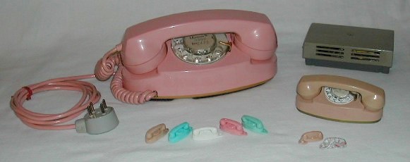 |
1959 -- Princess set as
announced -- 701B Number 8 "compact" dial External Ringer External transformer for dial light Night light switch on back An optional lead weight was added after release to help keep the phone from sliding while dialing. Shown with announcement-related premiums: mini sets and keychains. November, 1962 -- 702B announced Integrated a ringer into the base in place of the lead weight. For details on models produced, go here: PRINCESS SETS |
 |
ca. 1960 Princess Keyset concept Marked "Display Sample" - non-working (Image courtesy of AT&T Archives and History Center, San Antonio.) |
| Use this link to the Touch Tone Princess
Timeline To Touch Tone Princess Development Timeline |
|
Trimline development timeline -- announced in 1964 Design goal: Produce a set with the "Dial In Handset" See "The Evolution Of A Telephone," Bell Laboratories Record, January 1966. "From Butt Set to Beauty - The Trimline is 50 Years Old," Singing Wires (TCI), August 2015. "Another Branch on the Trimline Family Tree," Singing Wires, May 2019. |
|
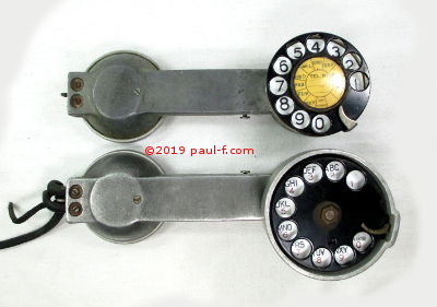 |
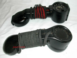
1920s - D-Specification Type Handsets (Test Telephones) Dial is positioned behind the receiver. Used within the Bell System and by independents. Components and construction vary by model variation. Some variations include: D-81760, D-81761, D-81762, D-81763 D-158318 D-75959 See: http://www.paul-f.com/weHandsets.html#Dspec |
 |
1926 Y-3091 Proposed Machine Switching Lineman's Handset Dial is positioned on the talking side of the hand test set. For detailed photos and descriptions of this set and the D-Specification sets, see: "Another Branch on the Trimline Family Tree," Singing Wires, May 2019. |
 |
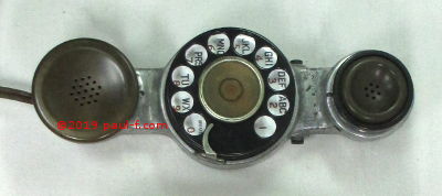
ca. 1934 Wood design model for a rotary lineman's test set. Contains real transmitter and receiver elements, but a mock-up dial. Final version, model 1011, first released in about 1939 is shown in the background. See: http://www.paul-f.com/weHandsets.html#1011 Mentioned in the 25th anniversary press release as the inspiration and starting point for the "dial in handset" project. |
 (Photo from BLR, Jan 66, p 10.) |
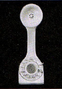
1952 Design model with dial in handset. The transmitter is in the center of the dial, so the user doesn't have t turn the handset around to dial. One piece telephone with switch hook button on the bottom. No ringer. Also mentioned in the 1989 Trimline 25th anniversary press release. |
 (Courtesy of Wayne Merit) |
ca. 1955 - 1956 Numerous design concept models were made from wood. Additional sets... |
 |
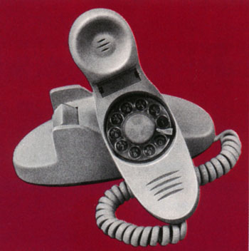
1957 F52578 8/57 - "Demitasse" The Trimline's design goal was to put the dial in the handset while having a very small base. Complex dial with transmitter in center. There was also a wall mount for this handset: F 58997 - "Demitasse" wall. Trials in San Leandro, CA and Columbus, Ohio. 400 sets in each city. Tested with Bedroom Set and Ericofon to determine customer preference for dial placement. Separate trial in Brooklyn, NY. 150 business and residential customers. Details... |
 (From a Bell System future products chart) |
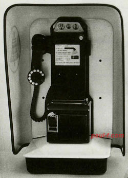
1958 Paystation with a dial-in-handset. |
 (Image courtesy of AT&T Archives and History Center, San Antonio.) |
ca. 1958 "Display sample" -- wood model Uses a ribbed fingerwheel, instead of one with holes. This design failed miserably in user testing, as fingers kept sliding out when dialing. The familiar holes were retained. |
  (From Bell Telephone Magazine, Jan/Feb 1968, courtesy of Jonathan Sowers.) |
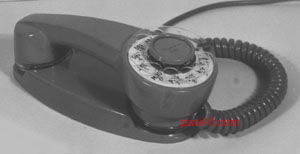
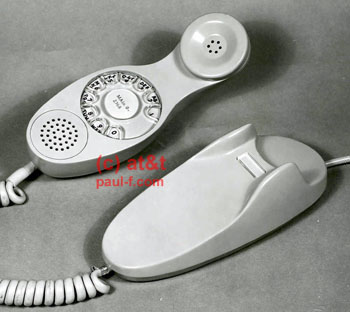
1959 F 53273 4/59, 6/59 - "Shmoo" F 53635 5/60 Receiver and transmitter were sealed in handset. Uses slots instead of holes over elements. Base works on desk or wall. Bulge in handset handle needed for dial. Note the space between 0 and 1 holes. Trials in New Brunswick, NJ. Details... |
 (From Bell Telephone Magazine, Jan/Feb 1968, courtesy of Jonathan Sowers.) |
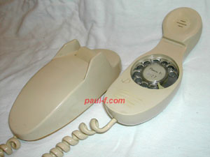
1960 F 53751 10/60, 11/60 - "Contour" Shaped like the "Shmoo" but narrower and slightly more compact. Used the compact dial with moveable fingerstop that was announced with the Trimline as the #10 dial to reduce the width of the handle. Trial in Richmond, VA, New Jersey and Pennsylvania. |
 (Courtesy of Lucent.) |
Trimline Wood design model Early concept for a moving fingerstop dial to reduce dial size, eliminating the bulge in the center of the handset. Note that the fingerstop is connected to the dial center. |
 (Courtesy of Wayne Merit) |
Trimline Wood design model Next generation, with the fingerstop in a more traditional position, along the rim of the fingerwheel. The contours on the handset and base are slightly more angular than the previous version. |
  (1962 Bell System ad, "No end to Telephone Progress") |
1960 F 53751 12/60 - Trimline ("Trimline I") F 53754 10/60 marked inside handset. Includes a prototype of the #10-style dial with moving fingerstop, and maintains the Shmoo-like horizontal vents for transmitter and receiver. The pins on the cradle are shown in their projecting position, for use as a wall phone. On the wood model above, they are shown retracted for desk use. Trial in Richmond, VA. |
 |
1962 F 54523 6/62 - "Carafe" wall phone Trimline-style, "space saver" dial with floating fingerwheel eliminates space between 0 and 1 holes. Dial face can tilt and swivel. Handset can be repositioned Product Trial in Providence, R.I. Details... |
  (Bell Telephone Magazine, Summer 1963) |
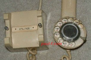
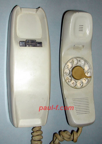
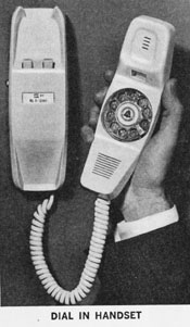
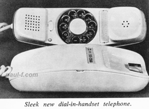
1963 F-55580 12/63 - "Dial-in-Handset," ("Trimline II"), desk set. Field trial version of the Trimline. There appear to be a few very minor differences compared to the final version, such as the added "recall" button and placement of fastening screws for the housing halves. Note the return to holes instead of slots used in the Trimline I above, the shape of the plunger and the slight ridge above the transmmitter. Product trial in 1963 in Royal Oak, MI, and market trials later in the year in Jackson, MI and Janesville, WI. Jackson trial allotment was increased from 1500 to 1800 in December. Trials lasted 6 months. Available in black and all standard colors. Details... |
 (BSP courtesy of the Pioneer Museum) |
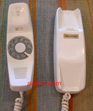
1964 F-56093 - "Dial-in-Handset," ("Trimline II"), wall set. Field trial version of the Trimline. BSP 502-150-900PT, Issue A, April 1964. Details... |
 |
1964 -- Trimline set as
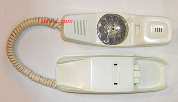
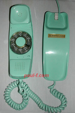
announced Smaller #10 dial with floating fingerwheel finally eliminated the bulge. Production handsets were marked 220A inside the handset's back cover. Bases were stocked seperately and mated with handsets at installation time. Installers could then mix and match to get a rotary or TouchTone handset with a desk or wall base. AC1 - wall base (shown here) AD1 - desk base (see TouchTone page) Wall base has a ridge to "park" the handset (shown). Desk base is shown on the Touchtone model here. Announced in the following colors (eventually available in all standard colors): Desk: beige, white, pink, blue and turquoise. Wall: beige, white, yellow and pink. |
| Use this link to the Touch Tone
Trimline Timeline To Touch Tone Trimline Development Timeline |
|
 (Courtesy of Lucent.) |
Message Waiting At least three alternatives were tested regarding location of a message waiting light for Trimline sets. 1. Two lights -- one on each side of the base. 2. In a cutout just above the handset cord on the handset. 3. Part of the plug on the handset end of the handset cord. Alternative 3 was chosen. It eliminated custom cuts to the handset and base plastic and the associated inventory issues. Having it in the cord also made it possible to easily add message waiting to any Trimline set equipped with a fifth conductor in the line cord jack. |
 (Top 2 photos courtesy of Lucent.)   (Courtesy of AT&T Archives and History Center, San Antonio.) |
Trimline Keyset bases 2 lines and hold F 57226 12/67 6-button keyset (for 1A2) F 57728 12/67 Wall mount base F 57227 11/67 (lacks key caps) |
| Other Rotary Models |
|
  - - - - - - - - - - - 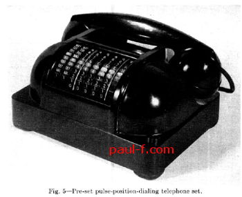 Set with later dial -- (BSTJ, May 1952) |
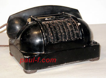
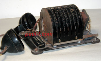
ca. 1940 Concept set with calculator-style dial for pre-set dialing The idea was to make the dialing process faster by having the user set the number in the wheels and let the phone control the dialing rate, with no wasted time between digits. [Similar to the way we now enter a complete phone number in our cell phones and hit SEND.] There are 7 large disks with pins along the edge, similar to some mechanical calculators of the day. Windows along the top show the currently selected digit. The first three have the appropriate 3 letter groups for exchange names instead of the digits 2-9. (e.g. ABC instead of 2) The coil and capacitor are mounted on the right side - dated 1940 and 1938. The housing is heavy cast metal, similar to the housings of the metal 300-series sets made at about the same time. The number was dialed when the handset was lifted. A reset button on the front right allowed the user to cancel the preset number to correct an error or set a new number. A number of similar sets, using the same housing were built into the mid-1950s, as part of a Bell Labs program to develop and test an experimental Electronically Controlled Automatic Switching System (ECSS). The goal was to test concepts that would minimize the holding time of central office resources by taking control of the dialing process away from the subscriber. The called number was pre-set using the levers, and the number was dialed using high-speed "pulse-position-dialing." This was clearly a laboratory experiment, and the signaling process was totally incompatible with existing equipment. There was no intent to put this system in regular service. Several patents were issued in the early to mid 1950s. Highlights of the system, including operational results, are included in the article, "An Experimental Electronically Controlled Automatic Switching System," Bell System Technical Journal, May, 1952, page 443. (Copy in the TCI LIbrary.) It's a very interesting read, if you are interested in switching systems. https://www.telephonecollectors.info/index.php/search?q=ECSS The article shows a later dial design, replacing the status windows above the dial with letters and numbers on the disk edges. Also, an 8th digit was added for a party line code -- J, M, R and W. |
 (Image courtesy of AT&T Archives and History Center, San Antonio.) |
ca. 1940 Concept set Cylindrical "pull down" dial designed by Clarence Lovell Note the layout: 8 9 0 5 6 7 2 3 4 1 Years after first seeing this photo I was able to research the project that created it plus a similar phone auctioned on eBay. Find the story in the three-part series titled "Why Build a Linear Rotary Dial?" in TCI's Singing Wires issues from March, April and May 2020. |
 ("Seventy-five Years of Progress", SNET, 1953) |
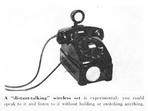
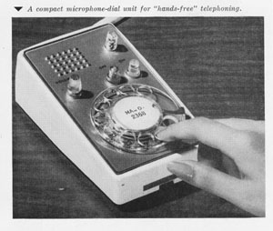
1953 "Distant Talking" Wireless Phone (Speakerphone) |
 (From The Reporter, July 1958) |
1958 "Fingertip" Executive Keyset Trial held with 25 executives in Bell Labs' Murray Hill facility. Included the 6-E Intercommunicating System. Keys are for outside lines or for direct calling to frequently used internal extensions. Includes speakerphone. |
 |
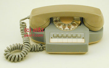
1960 Desk Drawer Set F 53530 2/60 Designed to be built into an executive's top side desk drawer. His desk could be neat and tidy, yet the phone would be convenient, when needed. This one includes a 6-button keyset, speakerphone and retractable handset cord. There's another example in the Experimental Phones Display. |
 (Image courtesy of AT&T Archives and History Center, San Antonio.) |
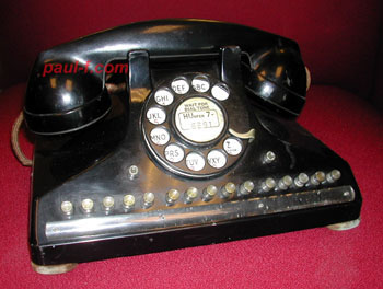
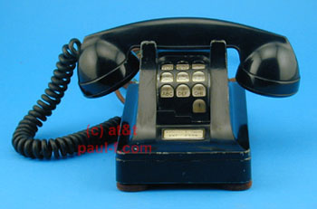
1962 F 55341 9/62 Modified 554 to include a 6-key strip and exclusion. Uses a single gong N-type ringer. There are more details and photos of the inside of this interesting phone in the October 2014 issue of Singing Wires from Telephone Collectors International. Back issues of Singing Wires are available on-line to TCI Members at: http://www.telephonecollectors.org/memberArea/ While you're there, check out the September 2014 issue. TCI Member Jim Schultz modified a standard 554 wall set based on this photo and tells how he did it. Info on TCI and how to join are found on their web site: http://www.telephonecollectors.org/member.htm |
 (Bell System ad, "Tomorrow's Telephones." ) 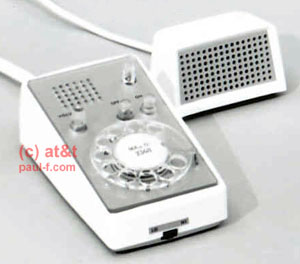 (Lower two images courtesy of AT&T Archives and History Center, San Antonio.) 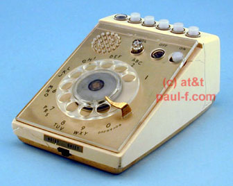 |
1962 Speakerphone Control Unit ("Capri"); with speaker from a Bell System future products photo (mid), and a "Display Sample" of the keyset configuration. (bottom) All require a small external speaker, suah as the model 758 shown. The small switch on the front adjusts sensitivity for noisy environments. |
 (Images courtesy of AT&T Archives and History Center, San Antonio.) 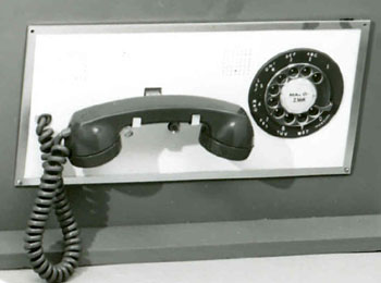 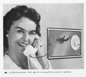 (Bell System ad, "No End to Telephone Progress," 1962) 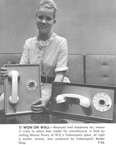 (WE News, 2/65) |
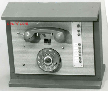
Panel Phones (Flush
mounted to wall) The first two photos are concept phones from about 1958. The first includes speakerphone and multi-line features. 1962 Panel Telephone Concept The set on the right went to Field Trial with the number F-53324A. The set on the left is the design that was produced as the model 750B. |
 (Image courtesy of AT&T Archives and History Center, San Antonio.) |
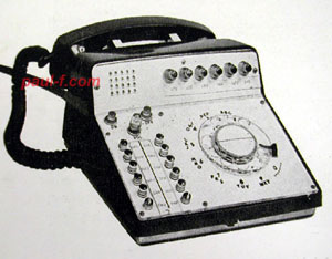
1962 Magnetic Dialer Telephone F-54165-A 50 number capacity. Rotate the dial on the right to select number, lift receiver and hit "call" button. 4 buttons in lower right are: dial tone, reset, record (red) and call. Field trial in Buffalo, NY. Also found in a 1962 Bell System ad, "No End to Telephone Progress." |
  (Image courtesy of AT&T Archives and History Center, San Antonio.) |
1962 Executive Telephone with Speakerphone. F 55076 9/62 Product trials in Chicago and Washington. 12 lines with hold and signal buttons. Line keys could be associated with outside lines or for direct access to frequently called internal extensions. Made in green, beige, gray and white. Required Executive Interphone switching system control unit. Never produced in volume. There was also a shorter version without the speakerphone. The cradle for the handset was across the dial, as on a Princess set. This one is marked "Display Sample" and is non-working. I'm looking for one! |
 |
CGS
Console
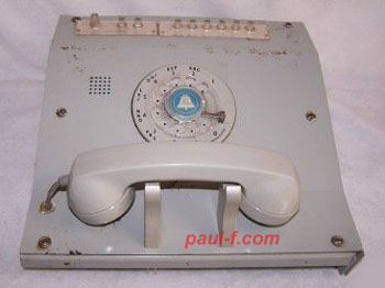
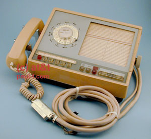
-- Unmarked, ca. 1960, Light Gray 8 display lights with no apparent way to change the status. INC ALERT STA BUSY READY DA OPR RE ORD White switch: RESET, TALK, IDLE. The dial is a fast (30pps) dial. Matches Figure 16-2 Attendant's telephone set in "The Electronic Switching System, Trial Installation, Morris, Illinois, General Description" published April 1960 by Bell Telephone Laboratories, Inc. Used for Attended CGS (Customer Group Services) to handle calls that are not completed automatically by direct inward dialing, or outgoing calls that require attendant services. INC = Incoming from outside CGS, ALERT = Action Required, STA = New call from a CGS station or tie line, or a recall, BUSY = Called CGS station is busy, READY = CGS station formerly busy is now idle and can be connected, DA = No Answer, RE ORD = Try again. Calls are handled by entering codes using the rotary dial. There are more details and photos of the inside of this interesting phone in the August 2012 issue of Singing Wires from Telephone Collectors International. |
 (Image courtesy of AT&T Archives and History Center, San Antonio.) |
1964 Wall keyset F56281 12-64 After a little contouring and a cradle redesign, this became the 851 set. For. a predecessor set and info on the evolution of 500-type wall keysets, check out the F55341 above. |
| Other
rotary
models are shown here: Tomorrow Calling Display |
Continue to TouchTone models |