 |
|
|
|
|
|
RELATED
PAGES
ON THIS SITE: COLORS
WE 300 DEVELOPMNT
TIMELINE
WE 500-SERIES WE 1500-SERIES WE 2500-SERIES |
|
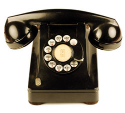
The basic design is found in models numbered from 250 to 466. During its lifetime, over 25 million sets were produced. The 300 series was Western's first desk set family that included the ringer, coil and capacitor in the base, forming a complete phone in one package. Previous models required an external subscriber set (subset), which contained these components. Base housings were made of metal from 1936-46. Thermoplastic housings were made from 1941-1954. The Family's life was extended into the 1960s as parts were refurbed in to the "modern" looking 5300s, which looked somewhat like the 500-series (announced in 1949). This page is intended to be a quick summary of the models produced and major functions. Western catalogs and technical documentation only show the models that were in production or service at the publication date. To understand the full scope of models produced we must compile data from many years of documents. Model Number, Suffix and Mounting Code Each phone has a 3-digit model number beginning with 2, 3 or 4. These are usually, but not always marked in ink on the bottom of the phone. If a model number is not found, look for a mounting code. Model numbers have suffix letters that define variations, such as manual/dial or number of mounting cord conductors. Some are defined below, but for details check the Bell System technical documentation (e.g. catalogs and BSPs - Bell System Practices). Mounting codes are assigned for combinations of mechanical and electrical features unique to each model. They are typically located near the rear cord hole, on the outside stamped into the metal on early sets and inside in red ink on later sets and thermoplastic sets. You can usually see the mounting code even if inside, by looking around the line cord or in the recess for the rear bottom plate screw. 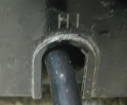 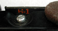 H1 mounting code on: outside of an early die cast zinc base and inside a later Tenite plastic base. Typical Suffix codes - e.g. 302CW (See each set's BSPs for details) A - manual B - dial, numbers only C - dial, numbers and letters D - dial, party line (letters JMRW) W - no Bell System markings If you're identifying a phone, you still need to check the internal components as many phones were refurbed and had internal components changed or removed. If done in a Bell System refurb facility, the code on the bottom was usually repainted or remarked. Many independent shops or field mods were not remarked with the accurate model number. NOTE: You can "search" for mounting codes or model numbers on this page by adding # and the code to the page URL. For example: http://www.paul-f.com/we300typ.htm#H1 http://www.paul-f.com/we300typ.htm#306 This is useful if you have found a mounting code on a set and want to find the model number, or know the model number and want to find the mounting code. For color information, see: Phones in color! For a chart showing component evolution on early 302 sets, see this chart prepared by Hal Belden. Most info in the chart below is from manufacturer catalogs and ads plus discussions on the ATCA and TCI Email Groups, and the Classic Rotary Phones Forum. No claim is made regarding accuracy or completeness. If you're enjoying looking at this level of detail and haven't joined one of the phone clubs yet, see the links page. This page is a work in progress. Please send comments, additions and corrections. Last update: 28 May 2024 |
| Photo |
Model, Mounting Code |
Major
Functions (all are desk sets unless noted otherwise.) |
BSP |
(External Photo: Same as 302 below) |
250 AA1 |
Common battery, no coil, condenser or
ringer. F1AW handset, D4U-9 mounting cord. Typically used as a desk stand replacement, where a magneto subset was already in place. e.g. replacing a D-series mounting or 20AL desk set. Catalog 11: "...intended for use in individual line, regular PBX extensions and bridged stations. Each set consists of a hand set, a telephone set mounting and the necessary cords and wiring. The telephone set mounting coded AA1-3 is the same as the NO. H1-3 Telephone Set Mounting except that the condenser, ringer and induction coil have been omitted. Each set, therefore, requires a suitable subscdriber set associated with it in order to complete the station equipment. If desired, the No. 250 type Telephone Set can be readily converted to the No. 302 type Telephone Set simply by adding the condenser, ringer and induction coil." 250AW: 82A-3 apparatus blank. 250BW: 5HA-3 dial and 59A dial adapter. 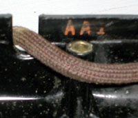 NOTE: For those searching for an "AA1" cradle phone, try looking for the A1 instead. http://www.paul-f.com/weHandsetMountings.html#A |
C32.301 Catalog 11, p.195 includes Wiring Diagram (Copy in the TCI Members' Area.) XXXXXXXXX Wiring Diagram in the TCI Library |
| 251 AB1 |
No
ringer or Bell System markings. F1AW handset, D3AL-9
mounting cord. Has a special mount for a harmonic
ringer. Typically sold to independents, who would add a
straight line or party line ringer as required. Catalog 11: " The No. 251 type TelephoneSets are intended for use in common battery manual or dial service on selective party lines using a harmonic ringer. Each set consists of a hand set, a desk type telephone set mounting, the necessary cords and wiring. The telephone set mounting coded AB1-3 is similar to the No. H1-3 Telephone Set Mounting except that it is furnished without a ringer and is provided with a special ringer mounting for a harmonic ringer." 251AW: 82A-3 apparatus blank. 251BW: 5HA-3 dial and 59A dial adapter. |
Catalog 11, p.195 Wiring Diagram in the TCI Library |
|
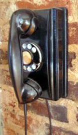
| 252 [none] |
Wall
set, No ringer or Bell System markings. F1AW
handset. Has a special mount for a harmonic ringer.
Typically sold to independents, who would add a straight
line or party line ringer as required. Catalog 11: " The No. 252 type TelephoneSets are intended for use in common battery manual or dial service on selective party lines using a harmonic ringer. Each set consists of a hand set, a wall type telephone set mounting, the necessary cords and wiring. This set is the equivalent to the 251 type Desk Set. The telephone set mounting is similar to the No. M3-3 Telephone Set Mounting except that it is furnished without a ringer and is provided with a special ringer mounting for a harmonic ringer." 252AW: 94A-3 apparatus blank. 252BW: 5HA-3 dial and 59A dial adapter. |
Catalog 11, p.196 Wiring Diagram in the TCI Library |
|
 (External Photo: Same as 325 below) |
300 [none] |
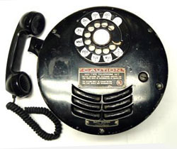
Outdoor
Use,
metal enclosure. Replaced by 325. E1D handset, 147A condenser, 149D condenser, 155B induction coil, 68L ringer. 300AW: 80A apparatus blank. 300BW: 4HA-3 dial. 300CW: 4hB-3 dial. 300DW: 4HE-3 dial. |
C55.251 (Description) C38.820 C65.857 502-410-400 Catalog 9, p.281 |
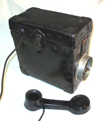 WE 301A with 1010A handset |
301 [none] |
Rugged, Portable magneto telephone. Several may be used on one line. Early set with issue 1 wiring diagram has a 1010A handset. Sets shown in catalogs have F3 handsets. 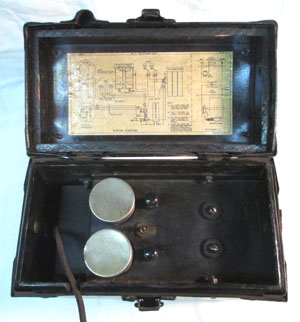 |
Found set NE Catalogs T7, p89 - 1947 T8, p166 - 1955 |
|
|
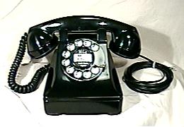
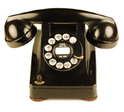
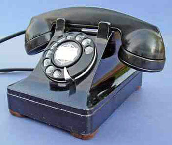
302 H1 |
Standard
Single
line
Desk Set, 101A coil, B1A ringer |
C32.502 C32.504 C38.551 C63.411 502-400-100 502-400-401 |
| 302AA, 302AC H13 (some found sets are marked H1) |
Party
Line "lift plunger to dial or talk" stamped in white
on cradle. Right plunger lifts. 101A coil, B1A
ringer. For a similar cradle, See Photos of the 307. |
C32.502 C32.504 502-400-100 502-400-400 |
|
| 303 H1 modified |
For
use at a Key Station - 1A key telephone system wiring
plans. 4-conductor mounting cord to separate ringer and talking circuits. 101A coil, B1A ringer. The H1 mounting is modified to prevent crosstalk. Induction coil equipped with 39A shield. |
C32.502 C32.504 C63.412 C63.416 |
|
| 304 H3 |
Tip-party
station
of message rate, automatic ticketing, and automatic
message accounting. 101B coil, B2A ringer |
C32.502 C32.504 C38.555 C63.413 502-400-402 |
|
 Photos from Tom Heckhaus 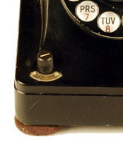 |
305 H4 |
Single
line, ringer cutoff switch marked "ON OFF" to
left of dial. 101A coil, B1A ringer |
C32.502 C32.504 C38.557 C63.413 502-400-100 502-400-403 |
|
(External Photo:
Same as 302 above)
|
306 H5 |
Party
line, 4-party selective, 8-party semi-selective. B3A
ringer, 195C Capacitor, 101A coil and 333A, 372A or 426A
electron tube. Variations: 306A (manual), 306B, 306C, 306D |
C32.502 C32.504 C38.559 C38.560 C63.414 502-400-100 502-400-404 502-400-405 |
| 306G H14 |
Party
line, 306 components plus a hookswitch labeled "lift
plunger to dial or talk". Right plunger lifts. For a similar cradle, See Photos of the 307. |
C32.504 502-400-100 502-400-406 |
|
|
(External Photo:
Same as 302 above)
|
307 H7 |
Local Battery talking, common battery
signalling antisidetone. For use on nonpolarized ringing
lines. B1A ringer, 387A capacitor, 104A coil, 266A
inductor. 307A may be wired to a magneto subscriber set (C38.565). Unusual party line modification has a hookswitch labeled "lift plunger to dial or talk" See Photos. |
C32.502 C32.504 C38.563 C38.565 C63.415 502-400-100 |
| 309 H12 |
Local
battery talking, common battery antisidetone signalling
set for use with 4-party selective and 8-party
semiselective services. It is similar to the 307 type
except that it employs the B3A ringer, 195A capacitor, and
in addition, a 405A or 426A electron tube. The
manual set is coded 309A and the dial set 309C |
C32.502 C32.504 C63.418 502-400-100 |
|
 |
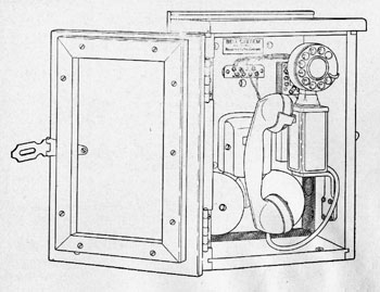
320 -- |
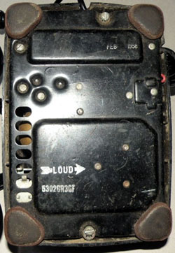
"Explosive
atmosphere."
Large round heavy wall set that screws onto a large mounting bracket. Works are in an inner compartment, so any sparks generated are contained. F6AR handset, later sets (or refurbs) used G11A handsets. Very similar to the later 520 shown here. |
C38.807 C55.152 502-415-100 502-415-200 |
  |
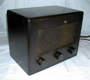
321 -- |
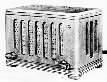
Provided
with
2A key telephone systems to furnish the loud speaking and
distant talking facilities at the master station. Apparatus is mounted on a metal chassis and enclosed in a walnut veneered cabinet. Three position volume control and talk/off/signal switch on front. Requires separate 112A tube amplifier. |
C53.161 C53.162 C53.164 502-410-400 502-560-100 502-560-201 |
 |
322 -- |
Elevator
- flush mount. Often mounted flush with the interior wall with a frame and glass or metal door. |
C38.815 C55.301 502-402-100 |
 |
324 -- |
Portable
set
in wood box for use on pierheads and vessels. 2-wire or 4-wire, 592 ringer (see below), and handset or head-chest set. |
C55.252 |
|
325BW - without
Bell System markings
|
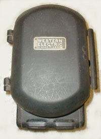
325 -- |
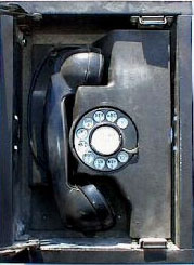
Outdoor, weatherproof - Door with rounded
top and bottom.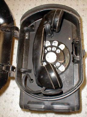 Several variations were
produced, some to fix problems with the
hookswitch. See the BSPs for details and wiring
alternatives.
The KS-8028 lock provided self-locking when the door was closed. For non-self locking, the lock was replaced with a KS-7861 lock. With no lock in place, the door was still self-latching, so would stay closed - although not secure. KS-8028 lock and key also used on the later 525 shown here. |
C55.251 (Description) C38.817 C38.818 C38.820 C65.857 502-410-400 502-560-100 502-560-201 |
 |
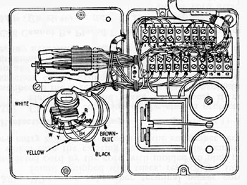
326 -- |
Outdoor,
weatherproof - Rectangular box enclosing a 211 set and 592
ringer. 592 Ringer
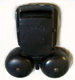 Basically a B1 ringer and capacitor in an enclosure. |
C55.251 C65.857 |
 |
328 S1 |
Single
line for use with M1 subscriber carrier system. Similar in appearance, but somewhat larger than, the 302 type. F1G handset, 14-conductor mounting cord, 5HB dial, 3 resistors, condenser, B3A ringer and multicontact switchhook. J98701A and M1S1 Subscriber Terminal use 2 of 10 channels for bidirectional communication over power lines to remote locations. |
C55.731 C55.735 WE Cat. 11 |
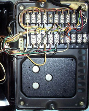 Photo from
Charles Ring
|
329 P339939 |
No
ringer, capacitor or coil. 4-Operating Spring hookswitch
with auxiliary spring (C32.575). 10-terminal
connecting block, D10D-9 cord and F2B handset.
Provision for separately ordered 7-type buzzer and 152A
capacitor. |
C32.502 C32.575 C38.802 502-400-407 |
 |
330 -- |
Provided
with
2B key telephone systems to furnish the loud speaking and
distant talking facilities at the master station. Apparatus is mounted on a metal chassis and enclosed in a walnut finished wooden cabinet. Power on/off switch, volume control and off/talk/signal switch and pilot lamp on front. Amplifies speech in both directions. |
C53.161 C53.162 C53.164 518-510-100 518-510-200 518-510-400 |
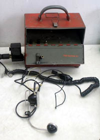 |
331 -- |
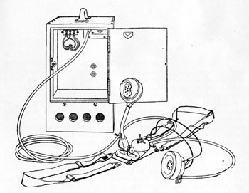
For
private lines, e.g. radio broadcasting 331A: In gray-green metal rectangular box with carry handle, contains magneto, batteries, 104A coil, cap and F3B-3 handset. 331B: Later set in bright blue with G5CR-3 handset. Sets made after 3/78 use a Trimline-style network on a printed circuit board. |
C32.516 C32.517 C38.803 C65.868 (Listserv) 510-810-100 |
 |
332 H8 |
Receiver
volume
control (right hookswitch knob has 3 marked positions - H,
M and L). Requires 4.5 vdc to power the amplifier. See photos. For more, see TCI's Singing Wires from June 1998, May 2004, and July 2010. |
C32.508 C54.111 C54.114 C65.113 502-400-100 502-400-408 |
| 334 H9 |
Receiver
volume
control (right hookswitch knob has 3 marked positions - H,
M and L), Requires 4.5 vdc to power the amplifier. For party line, polarized ringing. |
C32.508 C54.111 C54.114 C65.114 502-400-100 502-400-409 |
|
 |
352 M1 |
Wall,
Single line, 101A coil, B1A ringer [only made by NE, not WE (?), 1946-60] |
NE T-8 catalog, pp 155 - 156 502-400-100CA 502-400-410CA [Listserv] |
| 354 M3 |
Wall,
101B coil, B2A ringer. (Wall 304) Used at common battery antisidetone stations on nonpolarized ringing lines -- Individual lines, 2-party selective (flat or message rate), 4-party semiselective, divided code ringing, nonselective party lines, regular PBX stations, 755A and 750A keyless stations, 2-party automatic ticketing, 2-party flat rate, automatic message accounting and zone registration service. Note: 354C Special wall set modified for 2-line operation. See photos. |
C32.523 C32.509 C32.522 C38.575 C63.433 502-400-100 502-400-410 |
|
| 356 M5 |
Wall,
party line, 426A or 333A tube (ringer isolator for long
rural lines), B3A ringer, 101A coil. (Wall 306) Used at common battery antisidetone stations -- 4-party selective and 8-party semiselective service. |
C32.523 C32.509 C32.522 C38.577 C63.434 502-400-100 502-400-411 |
|
| 357 M7 |
Wall,
Local battery talking, common battery signalling, B1A
ringer, 104A coil, 387A capacitor, 266A inductor.
Used in same services as 354 except tip party dial message
rate stations. (Wall version of the model 307. See Photos of the 307 for component identification. The 266A is mounted to the left of the ringer in the 357.) |
C32.523 C32.509 C32.522 C38.579 C63.435 C63.289 502-400-100 |
|
 |
TP-6 -- |
WE 302-AW-3 set used in the military. Bottom plate secured by 2 screws. If converted to dial, usually has a TA-45-type dial by AE or Telephonics. |
Signal Corps TM 11-468 12/54 |
| TP-6-A -- |
Military version of 302. Designed
to be moisture resistant, fungus resistant and to keep
insects out of the set. Rubber grommets seal the
cord holes. Intended for use in damp tropical
climates (South Pacific, WWII). Bottom plate secured by 4 screws (different design than production 302s). Telephonics or AE dials used, with finger stop near the 6 o'clock position. See photos. |
C32.502 |
|
| D-173487 -- |
Modified version of the TP-6.
Used after the war in civilian applications where moisture
could be a problem, such as along waterfronts or marshy
lands, laundries, etc. When parts needed
replacement, standard 302 parts were used, including WE
dials. e.g.: Inductor: D-161107 (S-11-45) Ringer: D-161769 (S-7-45) Capacitor: D-171240, 2 mF 130v, 0.5 mF 200v. Dial: WE 5H (1-12-49) Bottom plate with 4 screws. No grommets on cords. F1 handset Once an original part is replaced with a non moisture-treated part, "These sets are treated as 302-type telephone sets." |
C32.502 C32.504 Found Sets |
|
| D-170901 -- |
Appears to be a military
variation -- uses the TA-45G/GT dial and was Fungus
Treated in June 1945. e.g.: Inductor: D-161107 (S-II-45) Ringer: D-161769 (S-6-45), modified B1A Capacitor: D-171658, standard size, rubber covered Housing dated S 511 45 F1W or D-173386 handset Wiring diagram in a found set is marked for use with D-167964 (manual), D-168869 (dial), and D-170901 (manual) Telephone Sets. 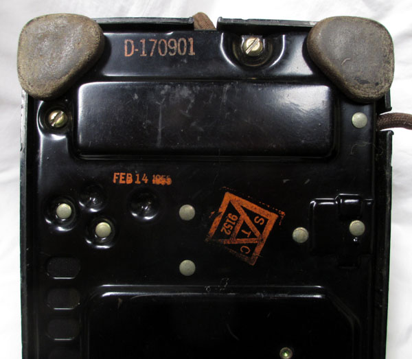  |
Found Sets |
|
| D-161583 -- |
Inductor: D-161107 (III 42) Ringer: D-161769 A wiring diagram shows a 6-conductor mounting cord, separating the ringer leads and providing an extra hookswitch contact closure -- probably for use with a PBX. 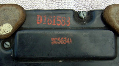 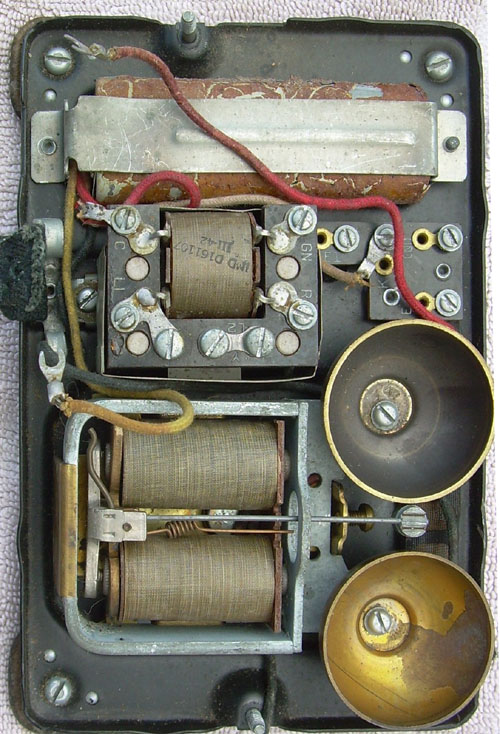 Photos from Doug Rose |
Found Sets | |
| SC5634A SC5687A D2993F D2993-G D2993-H D2993-L |
Sets with these
markings have been found. Note that SC5634A is marked on the D-161583 above. Sets marked D2993 all appear to have frequency ringers. the -G suffix may indicate a 50 Cycle ringer. the -H suffix may indicate a 66 2/3 Cycle ringer. the -L suffix may indicate a 42 Cycle ringer. Please send any additional found set markings or descriptive info. |
Found Sets |
 WE444
WE444| Photo |
Model, Mounting Code |
Major Functions (all are desk sets unless noted otherwise.) |
BSP |
 |
401 H6 |
single line with exclusion
key (right plunger lifts), for 1A KTS |
C32.525 C38.591 C38.592 C38.593 C53.151 C53.152 C53.153 C53.154 502-430-100 502-430-300 502-430-400 |
| 402 -- |
single line with exclusion
key (plunger lifts), for 1A1 or 1A2 KTS |
C32.511 C32.525 C38.591 C38.592 C38.593 502-430-100 502-430-300 502-430-400 |
|
 Photos from Tom Heckhaus 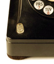 |
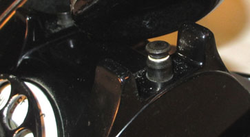
410 J1 |
2-line or KTS 1A system,
turn-switch on front left corner. Key can be wired for 2-line pickup or one line pickup with extension cut-off, ringer cut-off or headset control. Push button for signalling. Note: Earlier knobs were opaque. Later knobs were clear. Note: 354C Special wall set modified for 2-line operation. See photos. |
C32.511 C32.525 C38.591 C38.592 C38.593 C53.151 C53.152 C53.153 C53.154 502-430-100 502-430-300 502-430-400 |
| 411 J2 |
2-line or KTS 1A system,
turn-switch on front left corner - same as 410 plus exclusion key on plunger |
C32.511 C32.525 C38.591 C38.592 C38.593 C53.151 C53.152 C53.153 C53.154 502-430-100 502-430-300 502-430-400 |
|
| 412BC -- |
Secretarial service
(transfer line to secretary or answering service using
turn-switch) see WE Secretarial Sets |
C32.525 C38.591 C38.592 C38.593 502-430-100 502-430-300 502-430-400 |
|
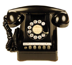
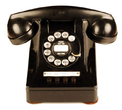 WE 440 - Showing opaque buttons Photos from Tom Heckhaus 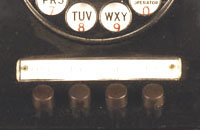 |
44x -- |
4-button keyset 440 = no lamps or exclusion (opaque buttons) 441 = no lamps, exclusion (pull up right plunger) 444 = lamps (clear buttons) 445 = lamps and exclusion (pull up right plunger) Buttons could be hold, pickup, signal or cutoff (turn button). Check the BSPs for details on the numerous variations and suffix codes. A good starting point is 502-435-100. Cutoff or Exclusion may be on a right turn button or the right plunger, depending on model. 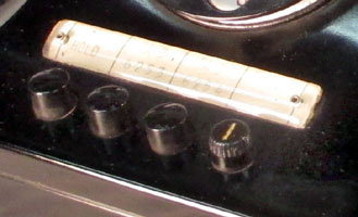
 |
C32.525 C32.601 C38.591 C38.592 C38.594 C53.151 C53.152 C53.153 C53.154 502-435-100 502-435-300 502-435-400 |
WE 464 -
Showing clear buttons
Photos from Tom Heckhaus 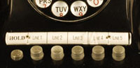 |
46x L3 L7 |
6-button keyset 460 = no lamps or exclusion (opaque buttons) 461 = no lamps, exclusion (pull up right plunger) (L3K) 464 = lamps (clear buttons) 465 = lamps and exclusion (pull up right plunger) (L7A) Buttons could be hold, pickup, signal or cutoff (turn button). Check the BSPs for details on the numerous variations and suffix codes. A good starting point is 502-435-100. |
C32.525 C32.530 C32.601 C38.591 C38.592 C38.594 C53.151 C53.152 C53.153 C53.154 502-529-400 502-435-100 502-435-300 502-435-400 |
| 462 466 L4 |
6-button keyset for use with 755A PBX. Only one set
of Tip and Ring go to the set, as line switching was done in
the PBX. 462 = no lamps (opaque buttons) (L4A) 466 = lamps (clear buttons) |
C32.530 C38.851 502-529-400 |
|
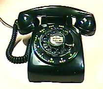
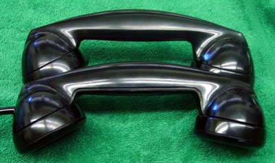
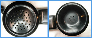
5300 series sets are 300 sets disguised as 500 sets. (Click photo above for a comparison.) The base and components
from a 300-series set were covered with a new
thermoplastic housing that looks similar to a
500-series set.
Since the bottom plate of the 300 is shorter than that of the 500, the housing is shorter and looks cut off in the back. 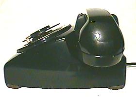
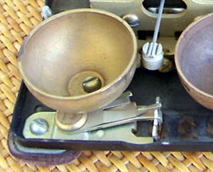
 The 3" dial is mounted in the housing, as on a 300 set. 5M or 6H dials included a black porcelain number plate with white dots, like the plate on the number 7 dials. A new double injection molded plastic number ring surrounds the dial, completing the disguise. 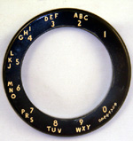  The 5302's normal handsets were a standard F1, or a "GF" handset that used a G1 handle with adapters and different caps for the HA1 and F1 elements used by the 300 series (Photos below). G1 or G3 handsets with the later T1 and U1 elements are also found, as are other G handset variations, such as a G6 amplified handset -- often supplied where their transmission characteristics were required, or added during refurb or by collectors. The cradle has a unique shape with depressions to accommodate the narrower F handset shape, as well as the G handset. 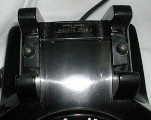 Another enhancement is a ringer volume control lever added to the B-series ringer, simulating the adjustment wheel on the 500 set's C-series ringer. 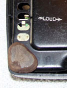
 Since most sets did not have the transmission characteristics of a 500 set, they were limited to installation in zones relatively close to the central offices. Housings from the mid-60s have been found, but may have been made as repair parts. The 1955 introduction date is found in several internal Bell System memos and articles, including an Events in Telecommunication History entry for August, 26, 1955, and a Bell Laboratories Record article, August 1956, page 313. BSP references start in 1956. Introduction was 6 years after the announcement of the 500-series. Contrary to the popular rumor, the 5302 was not the missing link "between" the 300 and 500 families, but was developed later to make productive use of the huge supply of 300 series parts that were within the Bell System. Subscribers could get a modern looking phone that looked like the 500, while the Bell System improved their return on investment. 5300 sets were not made "new" on the production line. Housings and ringer adjusters were installed on batches of sets that were returned for refurb. There is a great variation in the way sets were marked on the bottom -- both in color and location of the bottom stamping. Western Electric sold conversion kits with instructions to refurbishers. Like many other sets sold to independent phone companies, kits had housings marked Western Electric and without Bell System markings. Often refurbishers took short cuts, such as not marking the model number on the bottom or not installing the ringer adjustment hardware. Sets produced by independent refurbishers have been found with different model numbers, such as 5310. Note that dates on the set and internal components are usually those from the "donor" 300-series phone that was converted to a 5300-series set, and do not indicate the assembly or conversion date for the 5300-series set. 5300-series phones are difficult to date, as no assembly dates were usually indicated on the phone. The assembly date can generally be assumed to be after the date the housing was made. However, it is possible that the set was converted and then later refurbished with a newer housing. The models shown below were created from standard 300-series sets. A 5 prefix was added to the model number. Technical information can also be found in the BSPs for the original 300-series model number. |
|
* Also see the BSP for the basic
related 300/400 series set for details .
For color information, see: Phones in Color!
|
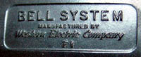
| Note: Handsets for use
within the Bell System were marked "Bell System". Handsets for use outside the Bell System were marked "Western Electric" and model numbers had a W suffix. e.g. F1W |
||
|
Model
|
Major Functions
|
BSP
|
 F1W 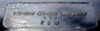 |
Standard handset for general use with 3-wire cord.
HA or LA series receiver and F series transmitter elements. F1W has no Bell System markings and was sold outside the Bell System. |
C32.203 C63.341 501-210-101 |
F2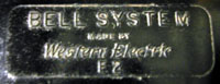 |
With 4-wire cord. Some have 289B dual phone plug for
PBX use where the operator preferred a handset to a headset. |
C32.203 C63.341 501-210-101 |
F3 |
With a pushbutton in the handle. For push-to-talk,
push-to listen, amplifier or external circuit control. |
C32.203 C63.341 501-210-101 |
F4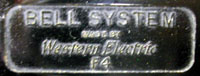 |
With G handset receiver element (U1 receiver and F1 or T1
transmitter) and 3-wire cord. For applications on long
loops. Some time between 7/54 and 2/56, the transmitter was changed from the original F1 to the later T1 with a spacing ring. |
C32.203 C63.341 501-220-100 501-230-100 |
| F5 |
With G handset receiver element (U1 receiver and F1 or T1
transmitter) and 4-wire cord. For applications on long
loops. Some time between 7/54 and 2/56, the transmitter was changed from the original F1 to the later T1 with a spacing ring. |
C32.203 C63.341 501-210-300 501-220-100 501-230-100 |
F6 |
For explosive atmospheres, 320 set and KS sets. HA1
receiver and K1 transmitter. |
C32.203 C38.807 C55.152 C63.341 501-210-101 502-415-100 502-415-200 |
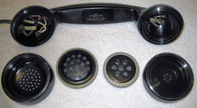
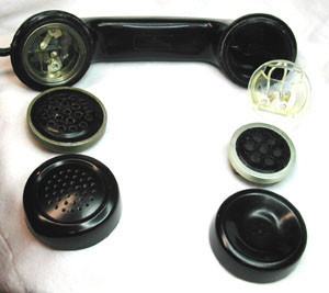
| GF (See photos below) |
Standard F1
handset elements in a G1 (or occasionally G3) handle with
special inserts and caps. For 5300-series sets. Receiver cap is marked "H" and Transmitter cap is marked "F" See photos below. |
502-400-301 NY |
TP6A |
The handle is stamped with
the US Government contract reference, and has no Bell System
markings. |
- |
| Link to similar info on G Handset Models. |
||
|
Handle Construction
|
Markings
|
Variation number.)
Terminal Arrangement
|
Handle Dates*
|
| SOLID CORE “UNGROOVED” | BELL
SYSTEM MANUFACTURED BY Western Electric Company |
1.) Separate R and BK terminals | 1936 (IV 36) |
| BELL
SYSTEM
MANUFACTURED BY Western Electric Company F1 |
2.) Separate R and BK terminals |
c.1936-37 |
|
| SOLID CORE GROOVED | BELL
SYSTEM MANUFACTURED BY Western Electric Company F1 |
3.) Separate R and BK terminals |
c.1937-39 |
| BELL
SYSTEM MADE BY Western Electric F1 |
5.) Separate R and BK terminals |
c. 1937-38 |
|
| Western
Electric Company U.S.A. F1W (For Independents) |
7.) Separate R and BK terminals |
c. 1937-38 |
|
| HOLLOW
CORE GROOVED |
BELL
SYSTEM MANUFACTURED BY Western Electric Company F1 |
9.) Wires running from receiver contacts to W and R. | c. 1940-42 |
| BELL
SYSTEM MADE BY Western Electric Company F1 |
10.) Wires running from receiver contacts to W and R. | post WWII | |
| Western
Electric Company U.S.A. F1W (For Independents) |
11.) Wires running from receiver contacts to W and R. | post WWII |
| Late production F-style handsets were made of
plastic, rather than the heavier bakelite. C32.203,
issue 8, August 1955 includes the following: 2.02 Lightweight F1-type handsets may be
distinguished from the regular handsets by their lighter
weight plastic, hollow handle, and an embossed dot
following the code number on the handle. Transmitter and
receiver caps for light-weight handsets are not
interchangeable with regular caps because the threads are
different. Caps for the heavier handsets have a number
molded in the center of the underside of the grid;
lightweight caps do not have such a number.
2.03 A lightweight handset should not be used to replace a regular handset. Its lighter weight may not operate reliably a switchhook designed for a regular handset. |

|
©2004-24 paulf. All rights
reserved.
|